User Manual VX4353 Relay Switching Module 070-9121-02 This document supports firmware version 1.00 Warning The servicing instructions are for use by qualified personnel only. To avoid personal injury, do not perform any servicing unless you are qualified to do so. Refer to the Safety Summary prior to performing service.
Copyright Tektronix, Inc. All rights reserved. Licensed software products are owned by Tektronix or its suppliers and are protected by United States copyright laws and international treaty provisions. Use, duplication, or disclosure by the Government is subject to restrictions as set forth in subparagraph (c)(1)(ii) of the Rights in Technical Data and Computer Software clause at DFARS 252.227-7013, or subparagraphs (c)(1) and (2) of the Commercial Computer Software – Restricted Rights clause at FAR 52.
Contacting Tektronix Product Support For application-oriented questions about a Tektronix measurement product, call toll free in North America: 1-800-TEK-WIDE (1-800-835-9433 ext. 2400) 6:00 a.m. – 5:00 p.m. Pacific time Or contact us by e-mail: tm_app_supp@tek.com For product support outside of North America, contact your local Tektronix distributor or sales office. Service Support Contact your local Tektronix distributor or sales office.
EC Declaration of Conformity We Tektronix Holland N.V. Marktweg 73A 8444 AB Heerenveen The Netherlands declare under sole responsibility that the VX4353 meets the intent of Directive 89/336/EEC for Electromagnetic Compatibility and Low Voltage Directive 73/23/ECC for Product Safety.
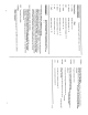
Appendix E – Performance Verification Procedure. . . . . . . . . . . . . . . . . . . . . . . . . . . . . . .
! $ # .
To avoid electric shock, tighten the module mounting screws after installing the module into the mainframe to ensure that the front panel is properly grounded. Note. There are two labeled printed ejector handles on the card. To install the card correctly, make sure the ejector labeled “VX4353” is at the top. Note. In order to maintain proper mainframe cooling, unused mainframe slots must be covered with the blank front panels supplied with the mainframe.
070-9121-02
Appendix E Performance Verification Procedure The performance verification procedure verifies that the module is operating within specification. Conventions Used In This Procedure All control of the VX4353 Module will be accomplished through a VXI Slot 0 device. ASCII characters will form the commands sent to control the module and ASCII characters will be read from the module.
Equipment Required Table 1–1 lists the equipment required for the performance and verification procedure. Table 1–1: Equipment Required Required tools and equipment Part number VXI Mainframe (such as the Tektronix VX1410) n/a VXI Slot 0 with resource Manager (Tektronix VX4521) and appropriate cables and interface cards. n/a Digital Multi Meter (DMM) with 4-wire Ohm capability, and standard lab equipment the ability to read more then 10 Gigohms.
Digital Multi-Meter Connection and Set Up 1. Connect the DMM signal high and input + side to the “pig tail” that is connected to the VX1780S connector pin-1. 2. Connect the DMM signal low and input – side to the “pig tail” that is connected to the VX1780S connector pin-2. 3. Set the DMM to the 4 wire Ohms mode, and select autorange. Testing The Relay Resistance 1. Send “C0lf” (Set relay CH00) to the VX4353. 2. Send “Q0lf” (Query relay CH00) to the VX4353. 3. Read “1 crlf” (Relay CH00 is closed). 4.
Testing The Delay Command 1. Send “Rlf” (Reset the VX4353) to the VX4353. 2. Send “D1000C0C1” (Reset, Close CH00 and CH01 on the VX4353) to the VX4353. a. Monitor the time difference between the time it takes for the CH00 LED to light, and the time for the CH01 LED to light. b. If working correctly, this time will be approximately 1 second. 3. Send “Tlf” (Delay Time of the VX4353) to the VX4353. 4. Read “1000 crlf” (Time Delay programmed to 1000 milliseconds).