Tele Radio Panther SAFETY INSTRUCTIONS 1 2 1 2 3 4 5 6 7 8 Standard settings LANGUAGE: ENGLISH (ORIGINAL) ARTICLE CODE: PN-R8-1, PN-T7-2 CE-IM-PN-RX002-A01-EN
Thank you for purchasing a Tele Radio product PN-R8-1, PN-T7-2 READ ALL INSTRUCTIONS CAREFULLY BEFORE MOUNTING, INSTALLING AND CONFIGURATING THE PRODUCT. These instructions are published by Tele Radio AB without any guarantee. These instructions are solely directed towards qualified installers. The instructions may be removed or revised by Tele radio AB at any time and without any further notice. Corrections and additions will be added to the updated versions of the instructions.
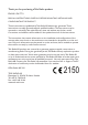
TECHNICAL DATA RECEIVER R8-1 (BASE BOARD) 7 8 9 10 11 12 13 LEDs 5 1 2 3 4 LED6 18 1 2 3 4 5 1. 2. 3. 4. 5. 6. 7. 8. 9. 10. 11.
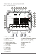
Current consumption RECEIVER MODEL SUPPLY VOLTAGE MAX. CURRENT CONSUMPTION R8-1 12-24 V DC <200 mA. Technical data FUNCTIONAL RELAYS: NUMBER OF CHANNELS: SIZE: WEIGHT: IP CLASS: FREQUENCY: 5 potential free* functional relays NO/NC 8A ACI 16 120 x 116 x 50 mm./ 4.7” x 4.6” x 2” 400 grams/ 14 oz. IP66 2405-2480 MHz. * Potential free means that you need to supply voltage to get power out of a relay (e.g. via a connection comb).
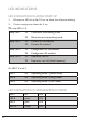
LED INDICATIONS LED INDICATIONS DURING START UP 1. All receiver LEDs lit up for 0.5 sec. to show that they are working. 2. Current settings are shown for 2 sec.
LED INDICATIONS DURING OPERATION LED 6 red LED 7 red ON Power to the receiver is on OFF Power to the receiver is off OFF No transmitter registered flashes (slow) At least one transmitter is registered and one transmitter is logged in, but not transmitting. flashes (quick) At least one transmitter is registered, but not transmitting. ON Valid radio packages from a registered transmitter received. ERROR INDICATIONS ON LEDS LED 7 (red) + LED 8 (yellow) ON Reading of production data failed.
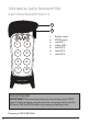
TECHNICAL DATA TRANSMITTER 8-BUTTONS TRANSMITTER T7-2 1 2 3 4 1 6 2 5 7 1 2 3 4 5 6 7 8 1. 2. 3. 4. 5. 6. 7. Rubber cover STOP button red LED 1 yellow LED red LED 2 red LED 3 red LED 4 STOP BUTTON TEST IMPORTANT! We recommend that the functionality of the STOP button is being tested at a regular basis: At a minimum, when used for 200 hours. Test the STOP button by pressing and pulling it out. Frequency: 2405-2480 MHz.
Technical data T7-2 transmitter NUMBER OF BUTTONS BATTERIES DEGREE OF PROTECTION NUMBER OF CHANNELS SIZE WEIGHT FREQUENCY 8 x 2-step pushbuttons 3 x 1.5V AA exchangeable IP65 16 7.3 cm. x 17.8 cm./2.9 x 7 in. (excl. rubber cover) 250 g./ 0.55 lbs. (excl. rubber cover, incl. batteries) 2405-2480 MHz. Install batteries 1. 2. 3. Remove the battery cover (2 screws). Put the batteries (3 x 1.5V AA batteries) in. Put back the battery cover (2 screws).
STANDARD SETTINGS DEFAULT STATE • • discontinuous radiotransmission no on/off function The system will start transmitting as soon as the batteries are inserted, the stop button is pulled out and a transmitter button is pressed. Radio transmission will end when no transmitter button is being pressed. START THE TRANSMITTER 1. Pull out the stop button. The transmitter transmits when a transmitter button is pressed. TURN THE TRANSMITTER OFF 1. Press the stop button.
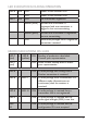
ERASE ALL TRANSMITTERS FROM THE RECEIVER 1. 2. Press the Function button until LED 7 lights. Press the Select button until red LED 1-5 light. Keep pressed until LED 7 and the relay LEDs 1-5 go out. NOTE! If red LED 7 flashes slowly, one or several transmitters are still registered in the receiver.
FCC IC INFORMATION The user is cautioned that changes or modifications not expressly approved by the party responsible for compliance could void the user’s authority to operate the equipment. Toute modification apportée à cet appareil qui ne serait pas approuvée expressément par (applicant name) peut invalider l’habilitation de l’utilisateur à utiliser l’appareil. This device complies with Part 15 of the FCC Rules and Industry Canada licence-exempt RSS standard(s).
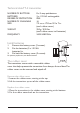
TRANSMITTER LABEL PLACEMENT + 2150 SN: XXXX FCC ID: ONFC1010A Pb IC: 4807A-C1010A Model No.: T00007-02 2 Model: T00007-02 eq.:2405-2480MHz Freq.:2405-2408MHz www.tele-radio.com 1 + This device complies with part 15 of the FCC Rules. Operation is subject to the following two conditions: (1) This device may not cause harmful interference, and (2) this device must accept any interfe ence received, including interference that may cause undesired operation. 1. 2. 3 IC ID label CE label 3. 4.
BATTERY PRECAUTIONS Observe the following general battery warnings. • As batteries contains flammable substances such as lithium or other organic solvents, they may cause heating, rupture or ignition. ! • Risk of explosion if battery is replaced with a battery of an incorrect type. • Do not short circuit, disassemble, deform or heat batteries. • Never try to charge a visibly damaged or frozen battery. • Keep batteries out of reach of small children.
ROHS AND WEEE In accordance with Directive 2002/95/EC on restriction of the use of certain hazardous substances in electrical and electronic equipment (RoHS) and Directive 2002/96/ EC on waste electrical and electronic equipment (WEEE), Tele Radio strives to minimize the use of hazardous materials, promotes reuse and recycling, and reduces emissions to air, soil and water.
TELE RADIO AB Sweden, Main office Tel. +46 (0)31-748 54 60 e-mail: info@tele-radio.com www.tele-radio.com TELE RADIO SVERIGE Sweden Tel. +46 (0)31-724 98 00 e-mail: sverige@tele-radio.com TELE RADIO GmbH Germany Tel. +49 (0)94 51-944 8 550 e-mail: deutschland@tele-radio.com TELE RADIO ASIA China Tel. +86-(0)592-3111168 e-mail: china@tele-radio.com TELE RADIO TURKEY Turkey Tel. +90 216 574 22 94 e-mail: turkiye@tele-radio.com TELE RADIO LTD England Tel. +44 (0) 1625 509125 e-mail: england@tele-radio.