Tele Radio 860 Lion INSTALLATION INSTRUCTIONS T00003-20 LANGUAGE: ENGLISH (ORIGINAL) ARTICLE CODE: RX1-A , RX2-A, RX3-A, RX4-A, T00003-20 FCC-IM-860-TX016-A01
Thank you for purchasing a Tele Radio product RX1-A, RX2-A, RX3-A, RX4-A, T00003-20 DOWNLOAD INSTALLATION INSTRUCTIONS FROM: www.tele-radio.com READ ALL INSTRUCTIONS CAREFULLY BEFORE MOUNTING, INSTALLING AND CONFIGURATING THE PRODUCT. These instructions are published by Tele Radio AB without any guarantee. These instructions are solely directed towards qualified installers. The instructions may be removed or revised by Tele radio AB at any time and without any further notice.
CONTENTS TECHNICAL DATA RECEIVER CURRENT CONSUMPTION CONNECT AND INSTALL THE RECEIVER 7 9 10 TECHNICAL DATA TRANSMITTER CHARGE THE BATTERY START THE TRANSMITTER TURN THE TRANSMITTER OFF 11 12 13 13 REGISTER THE TRANSMITTER IN THE RECEIVER ERASE THE TRANSMITTER FROM THE RECEIVER FREQUENCY SETTINGS 13 14 14 PLACEMENT OF LABELS WITH IC AND FCC INFORMATION 16 FCC STATEMENTS 17 RADIO TRANSMISSION 18 GUARANTEE, SERVICE, REPAIRS AND MAINTENANCE BATTERIES, ELECTRONIC
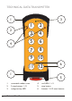
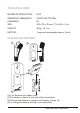
TECHNICAL DATA TRANSMITTER 1 2 4 3 1 2 3 4 5 6 7 8 9 10 11 12 1 1. 2. 3. 6 removable rubber cover 2-step buttons 1-12 red/green top LED Technical Data Transmitter 6 5 4. 5. 6.
TECHNICAL DATA DEGREE OF PROTECTION: IP 65 OPERATING FREQUENCY: 433.075-434.775 MHz CHANNELS: 69 SIZE: 200 x 70 x 35 mm./ 7.9 x 2.8 x 1.4 in. WEIGHT: 400 g./ 14.1 oz. BATTERY: 1 external, rechargeable battery (li-ion) CHARGE THE BATTERY 1a 1b 3 4 2 5 (1a+1b) Remove the rubber cover. (2)The battery is placed in the back of the transmitter. (3) Remove the battery to charge in the battery charger (4).
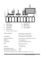
TECHNICAL DATA RECEIVER * Fuse S1, S2 and S3 ceramic slow S1: 200 mA. S2: 300-315 mA. S3: 500 mA.
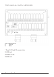
11 3 1 1. 2. 3. 4. 5. 6. 7. 2 4 5 6 7 8 Red LED 1 Yellow LED 2 Reset button Green LED 4 Red LED 5 Yellow LED 6 Function selector switch 8. 9. 10. 11. 12. 9 10 12 Green LED 8 Red LED 9 Yellow LED 10 Radio module Green LED 12 RELAY OUTPUTS: Midi: 10+2 for stop function Maxi: 24+2 for stop function STOP RELAY: Potential free*, makes 8A AC1 FUNCTION RELAY: Potential free*, breaks/makes 16A AC1 RADIO: PLL synthesizer. CHANNELS: 69 (433.075-434.775 MHz.
RECEIVER LEDS LED 2 lights yellow when the receiver has the correct supply voltage. LEDs 6 + 10 flash in yellow 1, 2 or 3 times, depending on how many transmitters that are registered in the receiver. LED 12 lights green when the receiver receives radio signals (433.075 – 434.775 MHz). LEDs 4 + 8 light green when a transmitter is logged in to the receiver. LEDs 5 + 9 light red to indicate a fault on the receiver. Contact your representative. Each relay has a LED that lights red when the relay is activated.
CONNECT, PLACE AND INSTALL THE RECEIVER NOTE! To utilize the safety of the system, use relays SR1, SR2 as stop relays in the safety circuitry of the object that you want to control. If the receiver is to be placed in a a hard-to-reach place, we recommend that you complete the settings in the receiver before mounting it. 1/2 Place the receiver: • as well away from wind, damp and water as possible. • with cable holders and vent plugs face down to prevent water from seeping in.
START THE TRANSMITTER 1. 2. Pull out the STOP button. Press the Start-buttons 11+12 at the same time for more than 1 second. The transmitter top LED lights. (With a PIN code: Enter the PIN code (4 digits). The transmitter top LED lights. TURN THE TRANSMITTER OFF 1. Press the Stop-button. NOTE! All relays deactivate when the stop button is being pressed. REGISTER THE TRANSMITTER IN THE RECEIVER 1-3 transmitters can be registered in each receiver. Each transmitter has a unique ID code.
ERASE THE TRANSMITTER FROM THE RECEIVER 1. Place the Function selector switch on the receiver in ON position. 2. Press the reset button on the receiver and keep pressed. 3. Release the reset button. Receiver LEDs 4, 8, 5, 9 go out. 4. Place the Function selector switch on the receiver in OFF position. 5. WITHIN 2 SECONDS: Place the Function selector switch on the Receiver LEDs 4, 8, 5, 9 light. receiver in ON position. Receiver LEDs 6+10 flash. 6.
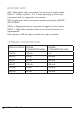
FREQUENCY TABLE 1 (69 CHANNELS) 01 02 03 04 05 06 07 08 09 10 11 12 13 14 15 16 17 18 19 20 21 22 23 24 25 26 27 28 29 30 31 32 33 34 35 433,075 MHz 433,100 MHz 433,125 MHz 433,150 MHz 433,175 MHz 433,200 MHz 433,225 MHz 433,250 MHz 433,275 MHz 433,300 MHz 433,325 MHz 433,350 MHz 433,375 MHz 433,400 MHz 433,425 MHz 433,450 MHz 433,475 MHz 433,500 MHz 433,525 MHz 433,550 MHz 433,575 MHz 433,600 MHz 433,625 MHz 433,650 MHz 433,675 MHz 433,700 MHz 433,725 MHz 433,750 MHz 433,775 MHz 433,800 MHz 433,825 MHz 43
PLACEMENT OF LABELS WITH IC AND FCC INFORMATION 1. FCC statement label 2. IC label 3. Product label 4. FCC ID label This device complies with part 15 of the FCC rules. Operation is subject to the following two conditions: (1) This device may not cause harmful interference, and (2) this device must accept any interference received, including interference that may cause undesired operation.
FCC STATEMENTS THIS DEVICE COMPLIES WITH PART 15 OF THE FCC RULES. OPERATION IS SUBJECT TO THE FOLLOWING TWO CONDITIONS: 1. THIS DEVICE MAY NOT CAUSE HARMFUL INTERFERENCE 2. THIS DEVICE MUST ACCEPT ANY INTERFERENCE THAT MAY CAUSE UNDESIRED OPERATION. NOTE: THE MANUFACTURER IS NOT RESPONSIBLE FOR ANY RADIO OR TV INTERFERENCE CAUSED BY UNAUTHORIZED MODIFICATIONS TO THIS EQUIPMENT. SUCH MODIFICATIONS COULD VOID THE USER´S AUTHORITY TO OPERATE THE EQUIPMENT.
BATTERY, ELECTRONICS, DISPOSAL AND RECYCLING PRECAUTIONS Observe the following warnings. • • • • • • • • • • • As batteries contains flammable substances such as lithium or other organic solvents, they may cause heating, rupture or ignition. Risk of explosion if battery is replaced with a battery of an incorrect type. Do not short circuit, disassemble, deform or heat batteries. Never try to charge a visibly damaged or frozen battery.
• Before using the transmitter for the first 3-4 times, make sure that the battery is fully charged. • When it´s time to charge the battery, the internal buzzer beeps 3 times, and the top LED turns red (when approx. 10% of the battery capacity remains). • The top LED remains red during charging. When the top LED turns green, the battery is fully charged ( approx. 4 hours). • The battery can not be overcharged. • We recommend that you use your battery at least once a month.
TELE RADIO AB Sweden, Main office Tel. +46 (0)31-748 54 60 e-mail: info@tele-radio.com www.tele-radio.com TELE RADIO SVERIGE Sweden Tel. +46 (0)31-724 98 00 e-mail: sverige@tele-radio.com TELE RADIO GmbH Germany Tel. +49 (0)94 51-944 8 550 e-mail: deutschland@tele-radio.com TELE RADIO ASIA China Tel. +86-(0)592-3111168 e-mail: china@tele-radio.com TELE RADIO TURKEY Turkey Tel. +90 216 574 22 94 e-mail: turkiye@tele-radio.com TELE RADIO LTD England Tel. +44 (0) 1625 509125 e-mail: england@tele-radio.