
User's Manual


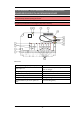

Table Of Contents
- Chapter 1: CUSTOMER INFORMATION
- Chapter 2: SAFETY INFORMATION
- Chapter 3: PRODUCT PAGES
- Chapter 4: INSTALLERS GUIDE
- Navigate in menu mode
- Enable PIN codes
- Create PIN codes
- Erase PIN codes
- Show registered PIN codes
- Start the transmitter in operating mode
- Start the transmitter in operating mode with PIN codes
- Turn the transmitter off
- Login/logout
- Register
- Erase
- Replace
- Automatic shutdown
- Frequencies & channels
- Relay functionality
- Digital inputs
- Chapter 5: OPERATING MODES
- Chapter 6: LOAD SELECT MODES
- Chapter 7: BATTERY GUIDE
- Chapter 8: CERTIFICATIONS CHAPTER

Expansion board:
15. Terminal block for analogue outputs 23. Function relays 22-25
16. Indication LED for communication with the
base board (green)
24. Terminal block for digital outputs
17. Programming connector
25. Terminal block for external analogue reference
and isolated analogue supply
18. Function button (Cancel) 26.Digital outputs LEDs
19. Select button (OK)
27. Indication LED for internal DC/DC converter
(yellow)
20. Terminal block for digital inputs
28. Indication LED for communication with the
base board (green)
21. Function relay LEDs (red) 29. Terminal block for analogue inputs
22. LEDs representing stop relays 1-2 and
function relays 1-7 on the base board
- 9 -