
Instruction Manual

32 Elkay Dr., Chester, New York 10918 (845) 469-4551 www.televue.com
Te l e V u e
Visionary
ENCODER INSTALLATION INSTRUCTIONS
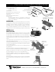
PARTS LIST
Altitude Encoder Assembly includes:
(1) Altitude encoder
(1) Delrin encoder housing
Azimuth Encoder
Delrin Azimuth encoder housing/scope stop
Main Wiring Harness (2 to 1 connector)
Pigtail Harness
Harness Junction Box with attached Velcro
Parts Bag includes:
(2) #10-32x3/8 button head screws, (1) #10-32x1-1/2" button head
screw, (1) #8-32x3/8" set screw, (1) #8-32x3/4" set screw, (1) 5/64
Allen Key, (1) 1/8 Allen Key.
INTRODUCTION
Thank you for purchasing the encoder kit which will allow you to connect the Sky
Tour computer to your Tele Vue mount. An additional Spacer Kit, product code
STS-5002, is required for installation of the azimuth encoder onto a Gibraltar5
mount. Otherwise the kit is identical for all mounts and attaches in the same
manner. The ability to add digital setting circles to these mounts adds a new level
of versatility and convenience while allowing you to further your astronomical
repertoire.
ENCODER SET-UP
Altitude Encoder AssemblyAltitude Encoder Assembly
Altitude Encoder AssemblyAltitude Encoder Assembly
Altitude Encoder Assembly
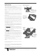
There should be a yellow or pink plastic shim between the edge of the altitude
encoder circuit board and the inside of the encoder cover. It is needed to prevent
mechanical “play” of the encoder within the cover, which would reduce the
encoder’s accuracy. Friction should hold it in position (shown in the photograph,
right) during shipping, but if it has fallen out, reinsert it lengthwise, beveled-corners-
end first.
1) Note alignment mark on top of left yoke arm (as seen standing behind the mount
head) Leave this altitude bearing alone
2) Using a utility knife blade, pry the name plate off the right side altitude bearing
cover. (As seen standing behind the mount head) This is the opposite bearing from
where the alignment marks are.
3) This will reveal 2 Allen key screws. Remove the screws and bearing cap with
the 5/64 Allen key.
4) Check the threaded hole in the right-side brass altitude bearing for a set-screw.
If no set-screw is found, use the #8-32x3/8" provided in the parts bag.
5) Make sure the plastic shim is still in place, then slip the shaft of the Altitude
Encoder Assembly fully into the hole in the center of the altitude bearing.
6) Using the 5/64 Allen key, tighten the set-screw against the encoder shaft.
7) Swing the Altitude Encoder Housing so the hole aligns with the threaded hole
in the Yoke Arm.
8) Thread the #10-32x1-1/2" button head screw into the hole to lock the Altitude
Encoder Assembly in place and snug up with the 1/8 Allen key. (No need to over
tighten.)
OVER
1/8 Allen Key
5/64 Allen Key
#10-32x3/8 Button Head
#10-32x1-1/2 Button Head
#8-32x3/8
Set Screw
#8-32x3/4
Set Screw
Parts not shown to scale
Pigtail
Main
Wiring
Harness
Junction
Box
Contents of Parts Bag
Delrin Azimuth encoder housing/scope
stop (underside showing cutout for azi-
muth encoder)
Azimuth
Encoder
32 Elkay Dr., Chester, New York 10918 (845) 469-4551 www.televue.com
Te l e V u e
Visionary
Hole for Altitude
encoder
Alignment
Marks
Screw holes for
Azimuth encoder
housing
Screw hole for
#10-32x1-1/2"
button head screw
Original
scope stop
Plastic Shim
Closeup
Altitude Encoder
Assembly
Plastic
Shim
#8-32x3/8" set-
screw location
#10-32x1-1/2"
button head
screw