
User Manual

32 Elkay Dr., Chester, New York 10918 (845) 469-4551 televue.com
Tele Vue
®
Visionary
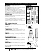
Parts Check List Parts Check List
Parts Check List Parts Check List
Parts Check List
(please check various bags for small parts)
•Gibraltar5 Mount Head (with mounting stud and altitude / azimuth encoders)
•Wood Tripod •Tray
•Eyepiece Caddy Set [with (4) ¼"-20 button head screws & (4) Thumb Knobs attached and
(2) 2"-1¼" Caddy Inserts installed]
•Sky Tour Caddy Plate •Sky Tour Computer [with (1) 9V Battery]
•Sky Tour Operating Guide, Sky Tour Database, & Harrington Field Guide
•Small-Parts Bags include: (1) Pigtail Wiring Harness, (1) Wiring Harness Junction box, (1)
Velcro strip for Junction box, (3) Rubber Tipped Studs for tripod legs, (2) Studs for scope
attachment, (1) 1/8" Allen Key, (1) 5/64" Allen Key, (5) Plastic Wing Knobs for scope and
tray attachments, (6) Leg Extension Lock Knobs, (1) Large "Star" Lock Knob, (1) Aluminum
"Washer", (2) #10-32 button head screws for Sky Tour Caddy Plate attachment, (1) 1/8" Allen
for Caddy Plate attachment, (2) Velcro strips for Sky Tour attachment, (4) 3/4" button head cap
screws, (2) 1-1/4" studs, and (1) 5/32" Allen.
Introduction & Use
The alt-azimuth mount Gibraltar5
TM
with Eyepiece Caddy Set and Sky Tour Computer system
is designed for the 5" Tele Vue-NP127 refractor.
The Gibraltar5 Mount Head cradles the telescopes at their centers of gravity to make
operation smooth and easy. It can also accept Eyepiece Caddy Set and Sky Tour system.
To achieve smoothest operation it is important to have the telescope properly balanced in its
mount ring and the altitude and azimuth tension knobs providing minimal drag.
The tripod legs can position the cradle height from 38" to 62". The triangular accessory tray
adds extra stability to the tripod.
Gibraltar5 is the ideal travel-friendly mount for quick, convenient terrestrial and astronomical
viewing.
Tripod, Head and Sky Tour Set-up
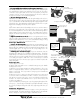
1)
Installing Foot Studs Installing Foot Studs
Installing Foot Studs Installing Foot Studs
Installing Foot Studs –After removing all packaging material, screw the Foot Studs into the
bottom of the Leg Extensions.
2)
Installing Leg Extension Lock KnobsInstalling Leg Extension Lock Knobs
Installing Leg Extension Lock KnobsInstalling Leg Extension Lock Knobs
Installing Leg Extension Lock Knobs –Screw Leg Extension Lock Knobs into the metal Leg
Clamp bands.
3a)
Setting-up on level groundSetting-up on level ground
Setting-up on level groundSetting-up on level ground
Setting-up on level ground –With the tripod upside down, pull the 3 Leg Extensions to the
same height and lock in place with Leg Extension Lock Knobs.
3b)
Setting-up on uneven terrainSetting-up on uneven terrain
Setting-up on uneven terrainSetting-up on uneven terrain
Setting-up on uneven terrain – Proceed as above, then install Tray (next step). Extend
remaining legs until head is approximately level. Lock Leg Extension Lock Knobs. Move on to
step 5.
NOTE: The mount only needs to be sufficiently levelled so the telescope swings smoothly in any
azimuth orientation.
4)
Installing TrayInstalling Tray
Installing TrayInstalling Tray
Installing Tray – With tripod right side up, spread apart tripod legs. Install Tray with edge
lip up. Insert the stud from one of the hinged Tray Supports through the hole in one corner of the
Tray. Secure Tray using one of the plastic Wing Nuts. (Leave Wing Nut slightly loose to ease
installation of the remaining Tray Support screws.) Mount Tray on the remaining two supports.
Tighten all three Wing Nuts after Tray is in position.
5)
Installing Gibraltar5 Mount Head on tripodInstalling Gibraltar5 Mount Head on tripod
Installing Gibraltar5 Mount Head on tripodInstalling Gibraltar5 Mount Head on tripod
Installing Gibraltar5 Mount Head on tripod – Place the long stud on the bottom of the
Gibraltar5 Mount Head into the hole in the Tripod head. Slip the 2" washer onto the protruding
stud from below. Thread on the large star-shaped knob and hand tighten to secure the mount
head.
Note Note
Note Note
Note: Mount head can be moved to a heavy-duty camera tripod by removing the mount
stud. Use 5/64" Allen to loosen
lower set screw on Azimuth bearing plate, then unscrew the
stud. Normally this set screw is tight to prevent stud from unscrewing from the head as mount is
turned in azimuth.
6)
Caddy Set Installation Caddy Set Installation
Caddy Set Installation Caddy Set Installation
Caddy Set Installation – Attach each Caddy bracket by passing the screws through the
clearance holes in the yoke arms and fixing the thumb knob tight. The angled edge will match
the arms, so that when viewing from the telescope eyepiece position, the three 1¼" holes will be
on the left side, while the two 2" holes with removable 1¼" plastic plugs will be to your right.
*LEAVE WING NUTS ON STUDS WHEN STORING SCOPE IN CASE TO PREVENT
RIPPING OF FOAM LINER.
GIBRALTAR5
TM
/ SKY TOUR MOUNT INSTRUCTIONS
WARN
IN
G:
Rotating the mount head
while the azimuth tension knob is tight-
ened could cause the azimuth bearing to
unscrew and separate.
Loose Parts in BagsLoose Parts in Bags
Loose Parts in BagsLoose Parts in Bags
Loose Parts in Bags
NP127 Ring
Plate supplied
with NP127
Fasten NP127
plate
underneath
cradle plate
with four ¼-20
button heads
Wing Nut