
Owner manual

2
1.0 Getting Acquainted with the Tele Vue-NP127is
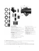
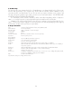
1.1 Optical tube assembly
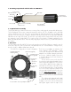
The NP optical design contains four elements consisting of two widely spaced, air-spaced doublet groups.
The forward group of lenses are contained in a stainless steel lens cell. The cell attaches to the main tube
via three alignment screws. The front cell is encased within the sliding dew shield. The rear doublet, mak-
ing up the rest of the objective, is larger in diameter than the previous NP127 and provides additional
illumination at the edge of the field. This benefit is especially useful for large format CCD chips which
are extremely sensitive to light fall-off. The rear lens group is housed in the cell that threads between the
back of the tube and the focuser. Never stick any long objects into the focuser or you will hit the rear-most
lens surface.
1.2 Focuser
The 2.4” output side of the NP127is focuser is designed to pass all of the field rays exiting the rear ele-
ments of the objective, as the forward end of the draw tube has a 3” internal diameter. A larger focuser,
therefore, lends no additional illumination benefit.
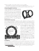
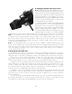
The NP127is is shipped in its “visual” configuration. The 2” Accessory Adapter sits within the 2.4”
inside diameter of the drawtube. Thumb
screws pass through both the drawtube and
adapter to cinch a brass clamp ring around 2”
accessories. With three thumb screws there
is enough holding power for the heaviest of
visual accessories!
The two tension screws on the top of the
focuser body can be adjusted to add resistance
when using heavy equipment. These tension
screws tighten against a brass clamp ring,
which then cinches down on the Teflon sleeve
in which the draw tube slides. For photography
it is not necessary to tighten beyond the need
to keep a camera stationary but we do recom-
mend to tighten them in unison to avoid any
focus shift. Note that even when sufficiently
tight, the focuser knobs can still drive the draw
tube.
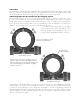
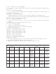
The end ring can be adjusted (and locked)
to compensate for any tilt effects seen in CCD
imaging. Lock screws in the end of the draw
tube tighten against either the taper of the
127mm Front
Lenses and Cell
Dew Shield in
retracted position
Main Tube
Rear Lens Cell
Focuser Body
Draw Tube
End Ring
Focuser Pinion Assembly
Lock Knob
Draw Tube Tension
Fine Focus
Coarse Focus
10:1 Knob
1:1 Knob
Lock Screws
(typical)
Jack Screws (typical)
Jam Screws
(typical)
Digital Indicator Kit
Mounting Points
1:1 Knob
Drawtube Tension
Screw (typical)
Focuser with 2” accessory adapter in place
2” Accessory
Adapter