
Owner manual

4
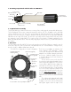
3.2 Finders
We particularly recommend using the Starbeam reflex sight (part# SFT-2003), which attaches to the Tube
Rings. The case has a cutout for the Starbeam. The Quick Release Universal Finder Bracket (QFM-1008)
can hold a traditional 50mm finderscope and also attaches to the mount ring channels.
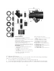
4.0 Photographic Set Up and the Tele Vue Imaging System
Tele Vue Imaging System Accessories provide solid threaded connections between components. To use
these accessories requires the insertion of the Imaging System Adapter (ISA) into the focuser. You will find
the ISA in the accessory compartment in the lid of the telescopes case. To install the ISA, first back off the
three Lock Screws far enough to pull the 2” Accessory Adapter out from the drawtube to reveal the 2.4”
diameter. Store the adapter in the accessory compartment in the case.
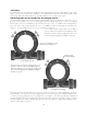
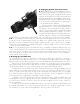
You will then need to back out the screws further
so their ends are flush with the inside diameter of the
End Ring. Insert the ISA and tighten the three Lock
Screws located equidistant around the end ring.
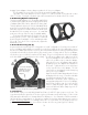
Conversion from visual (top) to imaging (bottom) con-
figurations. Remove 2” Accessory Adapter if present
and back off the three lock screws flush with the inside
ring. Insert the Imaging System Adapter and tighten
the three lock screws.
Arrangement for imaging.
Imaging System
Accessory Adapter
Visual adapter removed.
2” Accessory Adapter removed
and lock screws backed out.
The Imaging System’s threaded accessories provide a variety of options for camera adaptation and focal
length variation. The goal of Tele Vue’s Imaging System is to let you pursue your astrophotographic pas-
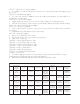
sion with ease, by providing accessories designed to work together. The following summary of parts and
pictorial diagram will help you understand each part’s use and its sequence in the chain. Please note that
spacing requirements of any particular camera will need to be met by the appropriate Imaging System
spacer or combination of spacers.