
Installation Instructions


TELECO AUTOMATION S.R.L.
ITALY
Tel. +39.0438.388511
info@telecoautomation.com
TELECO AUTOMATION FRANCE
FRANCE
Tel. +33.(0)472.145080
info@telecofrance.com
TELECO AUTOMATION GMBH
GERMANY
Tel. +49.(0)8122.9563024
info.de@telecoautomation.com
TELECO AUTOMATION OCEANIA PTY LTD
AUSTRALIA
Tel. +61.(07)5502.7801
info@telecoautomation.com.au
This document is the property of Teleco Automation Srl, which reserves all reproduction and copyrights
TELECO AUTOMATION BENELUX SPRL
BELGIUM
Tel. +32.(0)67561967
info@telecoautomation.be
In the view of a constant development of their products, the manufacturer reserves the right for changing technical data and features
without prior notice.
Teleco Automation Srl declares that the above mentioned articles satisfy the following technical regulations applicable:
- FCC (Federal Communications Commission Part 15 (FCC ID: P59TVTRX232-916) WARNING:
This device complies with part 15 of the FCC Rules. Operation is subject to the following two conditions:
(1) This device may not cause harmful interference, and (2) this device must accept any interference received, including interference
that may cause undesired operation.
(3) Changes or modications to this unit not expressly approved by the party responsible for compliance could void the user’s au-
thority to operate the equipment.
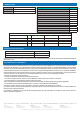
2. ERROR CODES:
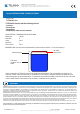
TECHNICAL SPECIFICATIONS
DECLARATION OF CONFORMITY
This equipment has been tested and found to comply with the limits for a Class B digital device, pursuant to part 15 of the FCC Rules.
These limits are designed to provide reasonable protection against harmful interference in a residential installation. This equipment
generates, uses and can radiate radio frequency energy and, if not installed and used in accordance with the instructions, may cause
harmful interference to radio communications. However, there is no guarantee that interference will not occur in a particular installation.
If this equipment does cause harmful interference to radio or television reception, which can be determined by turning the equipment
o and on, the user is encouraged to try to correct the interference by one or more of the following measures:
- Reorient or relocate the receiving antenna.
- Increase the separation between the equipment and receiver.
- Connect the equipment into an outlet on a circuit dierent from that to which the receiver is connected.
- Consult the dealer or an experienced radio/TV technician for help.
Error string 1 byte ‘E’
Error specic 1 byte X (from 0 to 9 see table II)
Checksum 1 byte Value
Error types: Hex Value
Framming error 0
Checksum error 1
Wrong command error 2
ID = 0 error 3
ID > 2000 error 4
Number of code to read/delete = 0 error 5
Number of code to read > 16 or >128 error 6
Number of code to read/delete > 2000 (out of range) error 7
Serial code already stored error 8
ID < 201 error 9
Empty location transmission attempt error 10
Value out of valid codes range memorization attempt error 11
Example 6: Error answer received
Data sent (hexadecimal): 41 01 F4 39 (see example 2):
‘T’ 500 wrong checksum
Answer received: 45 01 46
‘E’ checksum error checksum
Power supply 5 Vdc
Carrier frequency 916 MHz
Operating temperature range -10°C ÷ +55°C