E SERIES VoIP USER GUIDE For E100IP, E100IPLBY, E100IPTRM, E200IP, E200IPTRM, E103IP, E103IP RediDock, E203IP, E203IP RediDock
Important Safety Instructions When using your telephone equipment, basic safety precautions should always be followed to reduce the risk of fire, electric shock, and injury to persons, including the following: 1. Read and understand all instructions. 2. Follow all warnings and instructions marked on the product. 3. Unplug the product from the wall outlet before cleaning. Do not use liquid cleaner or aerosol cleaners. Use a damp cloth for cleaning. 4.
This equipment has been tested and found to comply with the limits for a Class B digital device, pursuant to Part 15 of the FCC Rules. These limits are designed to provide reasonable protection against harmful interference in a residential installation. This equipment generates, uses, and can radiate radio frequency energy and, if not installed and used in accordance with the instructions, may cause harmful interference to radio communications.
of any combination of devices subject only to the requirement that the sum of the Ringer Equivalence Numbers of all the devices does not exceed 5. REN: Z For warranty and service in Canada, please contact: Williams Telecommunications 5610 Kennedy Road Mississauga, Ontario, L4Z2A9 Canada Phone: 905-712-4242 Fax: 905-712-1754 Requirements of Part 15— FCC Rules Note: This equipment has been tested and found to comply with the limits for a Class B digital device, pursuant to Part 15 of the FCC Rules.
the customer as soon as possible. Also, you will be advised of your right to file a complaint with the FCC if you believe it is necessary. The telephone company may make changes in its facilities, equipment, operations, or procedures that could affect the operation of the equipment. If this happens, the telephone company will provide advance notice in order for you to make the necessary modifications to maintain uninterrupted service.
Table of Contents E100IP and E100IPTRM Phone Map. . . . . . . . . . . 7 E103IP and E103IP RediDock Phone Map. . . . . . 8 E200IP and E200IPTRM Phone Map. . . . . . . . . . . 9 E203IP and E203IP RediDock Phone Map. . . . . 10 Functions. . . . . . . . . . . . . . . . . . . . . . . . . . . . . . . 11 Standards and Protocols. . . . . . . . . . . . . . . . . . . 11 1. Introduction. . . . . . . . . . . . . . . . . . . . . . . . . . . 12 1.1 Overview of Hardware. . . . . . . . . . . . . . . . 12 1.1.1. . . . . . .
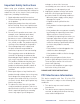
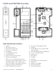
E100IP and E100IPTRM Phone Map BASE FEATURES AND CONTROLS 1. Handset 2. Wall mount clip slot 3. Wall mount handset clip 4. Actuator for hookswitch 5. LCD display 6. RJ-45 WAN input (POE) 7. RJ-45 LAN input 8. Ringer volume switch (unused) 9. Menu key (submerged) While it is not recommended, the Menu key may be used to program guest service/ speed dial numbers. (Press Menu, then press the numbers to be dialed, and finally end by pressing the speed dial key.) 10.
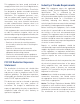
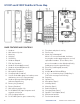
E103IP and E103IP RediDock Phone Map BASE FEATURES AND CONTROLS 1. Handset 2. Wall mount clip slot 3. Mute key 4. Hold key 5. On/Off key 6. Handset dialpad 7. FNC key (handset) 8. Handset volume s (increase) 9. Handset volume t (decrease) 10. Redial key (handset) 11. Microphone (handset) 12. Charging leads (handset) 13. Screws and rubber plugs for handset cover and battery access (in separate bag) 14. Handset Message Waiting/Ringing Indicator/Speaker key 15. Battery tray (handset) 16.
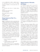
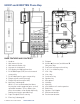
E200IP and E200IPTRM Phone Map BASE FEATURES AND CONTROLS 1. Handset 2. Wall mount clip slot 3. Wall mount handset clip 4. Actuator for hookswitch 5. LCD display for MWI and interface 6. RJ-45 WAN input (POE) for voice network connectivity 7. RJ-45 LAN Input for guest connectivity 8. Ringer volume switch (unused) 9. Ringer Hi/Low (unused in VoIP) 10. Menu key (submerged) While it is not recommended, the Menu key may be used to program guest service/ speed dial numbers.
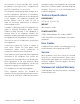
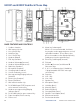
E203IP and E203IP RediDock Phone Map BASE FEATURES AND CONTROLS 1. Cordless handset 2. Wall mount clip slot 3. Line 2 On/Off key 4. Hold/Conf key 5. Line 1 On/Off key 6. Handset dialpad 7. FNC key (handset) 8. Handset Volume s (increase) 9. Handset Volume t (decrease) 10. Redial key (handset) 11. Microphone (handset) 12. Charging leads (handset) 13. Screws for battery access 14. Message waiting/Ringing indicator (handset) 15. Battery tray (handset) 16. Battery (handset) 17. Wall mount handset clip 18.
Functions Standards and Protocols • Support failover connection to a redundant SIP server • Support NAT (Network Address Translation), Firewall • Support DHCP for phone to accept IP via WAN port or assign IP address via LAN port • Support PPPoE (used when connecting the ADSL or cable modem) • Update the firmware and/or configuration file program through HTTP, FTP, and TFTP • Hold function • Hotline function (dial a specific number as soon as going off-hook or set a delay before dialing) • Speed-dial • Cal
1. Introduction This is the User Guide for the E Series VoIP phone. This phone is a standard SIP (Session Initiation Protocol) phone, and some configuration is necessary before it is ready for use. This manual will illustrate how to set up the phone through keyboard and Web User Interface (UI). 1.1 Overview of Hardware 1.1.1 The two RJ-45 network interfaces support 10/100M Ethernet. The default WAN interface is a DHCP Client.
2. Handset Keys for E Series 2.
3. Web Browser User Interface to Configure the Phone In most cases, the phone will obtain an IP address from the local DHCP server. You may find this IP address from the phone by using a simple diagnostic code. On the phone’s dialpad, press * * 4 7 # (* * I P #). The phone will read out the IP address (and display it on the LCD if the phone has a screen).
Configure to dynamically obtain the IP. Enable DHCP. If there is a DHCP server in your local network, the E Series phone will automatically obtain the WAN port network information from your DHCP server. CONFIGURE PPPOE – Enable PPPoE – PPPoE Server: Enter “ANY” if not specified from your ITSP – Enter PPPoE username and pin in the Username and Password entries The E Series phone will automatically obtain the WAN port network information from your ITSP if the PPPoE setting and the setup are correct.
Enable Register: Enable/Disable SIP register. The E Series phone won’t send registration information to the SIP server if the register is disabled. Display Name: This field will display the User Agent (UA) in the header. Proxy Server Address: IP address of proxy SIP server. (A SIP provider usually uses the same IP for the register server and the proxy server. In this case you don’t need to configure the proxy server information.) Proxy Server Port: Signal port of the SIP proxy.
most IP/PBXs, but some vendors (Avaya CM) recognized “Send */#”. Media Key: Not environments. applicable in Hospitality RFC Protocol Edition: SIP versions are identified by the IETF (Internet Engineering Task Force). SIP version 1 is RFC 2543. The default is the newer SIP 2 RFC 3261. An example of when you might revert back to RFC2543 is if the gate needs to communicate to older devices (such as CISCO5300) using the SIP 1.0 (RFC2543 protocol). Default is RFC 3261.
avoidance parameters of TCP connections over high-bandwidth, high-latency networks. Click to Talk: Not applicable in Hospitality environments. The default is unchecked/disabled. 3.5 Advance 3.5.1 DHCP SERVER DHCP Lease Table: Shows the IP-MAC corresponding table assigned by the DHCP server. Note: This setting won’t take effect unless you save the configuration and reboot the device. 3.5.
Network (LAN). An external attacker only has access to equipment in the DMZ, rather than any other part of the network. The name is derived from the term “demilitarized zone,” an area between nation states in which military action is not permitted. Use STUN: The STUN setting that allows (enables) or forbids use. 3.5.4 NET SERVICE 3.5.3 STUN CONFIGURATION This page is used to set the private SIP server, STUN server, and back up SIP server information.
E Series firewall filter is the base WAN port. So the source address or input destination address should be the WAN port IP address. FIREWALL CONFIGURATION In_access Enable: Enables the in_access rule. Out_access Enable: Enables the out_access rule. Input/Output: Select rule type input rule or output rule. Deny/Permit: Select rule type deny rule or permit rule. Protocol Type: Protocol used in this rule: TCP/IP/ ICMP/UDP. Port Range: Port range selections are more than, less than, equal, or not equal.
IMPORTANT: Voice/Data VLAN differentiated IS ALWAYS SET TO “Undifferentiated” in the drop down menu. DiffServ Value: The value range: 0x28,0x30, 0x38,0x48,0x50,0x58,0x68,0x70,0x78,0x88,0x90,0x 98,0xb8. (Default is 0xb8.) 0xb8 stands for best fast transmission. 28–38 is for the transmission priority of the first rank. 48–58 is for the transmission priority of the second rank. 68–78 is for the transmission priority of the third rank. 88–98 is for the transmission priority of the fourth rank. Data 802.
ELEMENTS IN A DIAL PLAN PATTERN: X Matches any dialed digit, #, or * 0–9, *, # Matches the digit [] Matches any one of the digits between brackets , Play a secondary dial tone if the patter up to this point has been matched, e.g. “9,1xxxxxxxxx” means play a dial tone after a 9 is entered. Tn Additional digits may be dialed, but the pattern will be matched when n seconds elapse with no further dialing IN THE U.S., A RECOMMENDED MINIMUM DIAL PLAN INCLUDES: Hot Line: Configures the hotline number.
3.5.9 MEMORY KEY PROGRAMMING 3.5.9.2 CALL-PARK/RETRIEVE This page layout shows the phone numbers used by the speed dial keys. There are several special functions that can be programmed into the memory keys, such as Transfer, Transfer-Silent, and Call-Park/Retrieve. Call-Park/Retrieve allows the phone’s user to send a call to a ‘Park’ location (setup within the PBX), where another user may then ‘Retrieve’ the call from a different phone. It is programmed as follows in two steps: 1.
3.5.10 MMI FILTER The MMI filter is used limit access to the E Series phone. When an MMI filter is enabled, only the IP addresses within the start IP and end IP can access that E Series phone. 3.5.11 DSP CONFIGURATION/AUDIO SETTINGS Ring Volume: The volume of the alerting ring as heard by the called party. G729 Payload Length: G729 payload length. G.729 is an audio data compression algorithm for voice that compresses digital voice in packets of 10 milliseconds duration.
Update Configuration: Update the current configuration through configuration files. Note: Clearing the configuration in admin mode restores all settings to factory default. Clearing the configuration in guest modem restores all settings to factory default except SIP and advanced SIP. 3.7 Update Firmware obtain the configuration file from your updated server if it is configured. To obtain the original configuration file, you can use the FTP/TFTP back up as described above.
For instance: <>Version: 1.0000 ConfFile Version: 6 and we recommend using the free software Wireshark for capturing network data packets instead of Syslog. Warning: if the power is cycled on the phone, Syslog is set back to its default “off” state. User may edit the configure file version to: Click “Apply” after setting this up. <>Version: 1.0007 ConfFile Version: 7 3.8.3 PHONE BOOK Gateway original version is: 3.
Server: Enter the IP address of the SNTP time server. Time Zone: Select the correct time zone from the list in the box. 4. Operating Method for Dialing Time Out: The longest response time for SNTP server. 4.1 How to Dial an IP Phone 12 Hours Format: Select the 12 hours format. Daylight: Whether Daylight Saving Time is being used. You can make a call after your phone is properly set up.
CONFIGURE STATIC IP – Choose Static – Fill in the IP address of the E Series phone in the Static IP Address field – Fill in the subnet mask in Netmask – Fill in the router address or up Gateway address in the Gateway – Fill in the local DNS server address in the Primary DNS and Alter DNS respectively Server Address: This is the IP address or FQDN (Fully Qualified Domain Name) of the IP/PBX SIP Registration server. Server Port: This is the Internet Socket Port for SIP information.
Enable Message Waiting: (usually enabled)—The configuration allows or forbids Message Waiting. Note: Choose Save Configuration in the Configuration Management window after setting up the new information or the existing setting information will be reset when the phone is rebooted. Reference—Quick Keys The Teledex family of SIP phones has implemented an innovative way to determine various states of the SIP phone and the network it is attached to via the phone’s dial-pad.
Reference—SIP Quick Start to Register a Single Phone The Server Address of the IP/PBX, Extension Number/Account Name, Phone Number, Display Name, Enable Register, and Enable Message Waiting indicators are all programmed here. Speed Dial and OneTouch Message Keys Are Programmed Under Advance -> Memory Key The Cetis, Inc., SIP phones are SIP-only endpoints powered only by POE/802.3af and will acquire an IP address when connected to a DHCP server. Begin by plugging your POE Ethernet cable into the WAN port.
Reference—IP DECT Handset/Base AutoSync Registration Register Up To 4 Additional Handsets It is possible to register up to 4 additional remote handset kits to a single base station. Repeat the process above for three more handsets (LEAVE BATTERIES IN ALL HANDSETS). The IP-DECT cordless hospitality phones have a base station that is powered via POE 802.3af. The max power consumption is 3.5W, thus falling into the POE class spectrum of Class 2.
Toll Free: +1.800.462.9446 Tel: +1.719.638.8821 Email: info@teledex.com www.teledex.com © 2013 Cetis, Inc. Product specifications and descriptions in this document subject to change without notice. CetisTM, Teledex®, TeleMatrix®, Scitec®, ExpressNet®, and Teledex iPhoneTM are trademarks or registered trademarks of Cetis, Inc.