Instruction Manual CP150 Current Probe
CP150 Current Probe Instruction Manual January 2013
700 Chestnut Ridge Road Chestnut Ridge, NY, 10977-6499 Tel: (845) 425-2000 Fax: (845) 578 5985 teledynelecroy.com © 2013 Teledyne LeCroy, Inc. All rights reserved. Unauthorized duplication of Teledyne LeCroy documentation materials other than for internal sales and distribution purposes is strictly prohibited. However, clients are encouraged to distribute and duplicate Teledyne LeCroy documentation for their own internal educational purposes.
Instruction Manual TABLE OF CONTENTS Safety Instructions ..........................................................................................................................................................1 Symbols .................................................................................................................................................................... 1 Precautions ...............................................................................................................
CP150 Current Probe Preliminary Procedure............................................................................................................................................. 12 Adjust LF Accuracy ................................................................................................................................................. 12 Specifications ...............................................................................................................................................
Instruction Manual Safety Instructions This section contains instructions that must be observed to keep this oscilloscope accessory operating in a correct and safe condition. You are required to follow generally accepted safety procedures in addition to the precautions specified in this section. The overall safety of any system incorporating this accessory is the responsibility of the assembler of the system.
CP150 Current Probe Be careful not to damage the insulation surface when making measurements. Never install or remove the probe on bare conductors which are energized. The transformer core and shield are grounded but not insulated and may contact the conductor when the locking lever is open. To avoid short circuits and accidents that could result in injury or death, use the CP150 current probe only with conductors carrying 300 V or less.
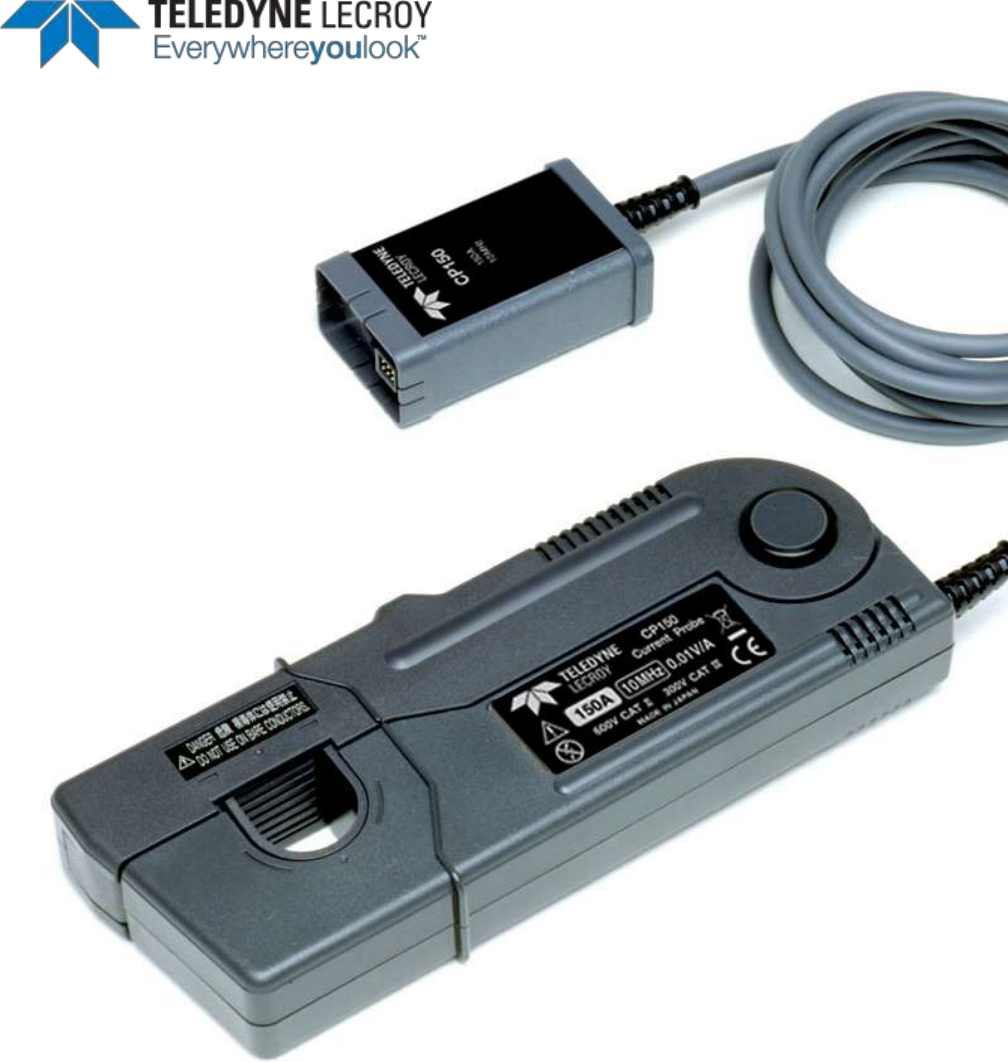
Instruction Manual Overview Description The CP150 uses a combination of Hall effect and transformer technology which enables measurements to be made on DC, AC and impulse currents. It has a 10 MHz bandwidth and is designed to measure continuous currents up to 150 Amp. The probe can be used with a WaveRunner, LC, and WavePro series oscilloscope with firmware 4.3.0.0 or higher. With the ProBus interface, the CP150 becomes an integral part of the oscilloscope.
CP150 Current Probe Operation Precautions The sensor head is a precision assembly consisting of a molded component with a ferrite core and a Hall effect element. It may be damaged if subjected to sudden changes in temperature, mechanical strain or shock. The mating surfaces of the sensor are precision ground and should be treated with care. If there is any type of dust or dirt on the mating surfaces of the sensor head, measurements may be impaired.
Instruction Manual Operation with a Teledyne LeCroy Oscilloscope The probe can be controlled through the Vertical Setup dialog for the channel to which the probe is connected. Turning the VOLTS/DIV knob will control the oscilloscope’s scale factor to give full dynamic range from 20 mA/div to 50 A/div.
CP150 Current Probe Care and Maintenance Cleaning The exterior of the probe and cable should be cleaned only using a soft cloth moistened with water or isopropyl alcohol. The use of abrasive agent, strong detergents or other solvents may damage the probe. CAUTION. The probe case is not sealed and should never be immersed in any fluid. Calibration Interval The recommended calibration interval is one year. Adjustment should only be performed by qualified personnel.
Instruction Manual Returning a Defective Probe Contact your local Teledyne Lecroy sales representative to find out where to return the product. All returned products should be identified by model number and serial number. Provide your name and contact number and if possible describe the defect or failure. In case of products returned to the factory, a Return Authorization Number (RAN) must be used. Contact your nearest Teledyne Lecroy office, or the New York Customer Care Center, to receive a RAN.
CP150 Current Probe Performance Verification This procedure can be used to verify the warranted characteristics of the CP150 Current Probe. The recommended calibration interval for the model CP150 Current Probe is one year. The complete performance verification procedure should be performed as the first step of annual calibration. Performance verification can be completed without removing the probe covers or exposing the user to hazardous voltages.
Instruction Manual Description Minimum Requirements Test Equipment Examples Function Generator 50 Hz sine wave output 3 Vrms into 50Ω Agilent Technologies 33120A or Stanford Research Model DS340 Calibration Fixture, 500 Turn Loop 500 Turn loop in series with 0.5Ω ± 0.
CP150 Current Probe Check LF Accuracy Figure 1. LF Accuracy Test set up. 1. Set the Function generator to 50 Hz sine wave. Output voltage at 1.7 Vrms with 50Ω output. 2. Remove the CP150 from the oscilloscope and reconnect using the ProBus extension cable. Connect the BNC male connector of the ProBus extension to DMM #1 using a BNC Female to Dual Banana adapter. 3.
Instruction Manual Adjustment Procedure This procedure can be used to adjust the warranted characteristics of the CP150 Current Probe. This procedure should be used if a parameter measured in the Performance Verification Procedure is outside of the specification limits. Adjustment should only be performed by qualified personnel. The warranted characteristics of the CP150 Current Probe are valid at any temperature within the Environmental Characteristics listed in the Specifications.
CP150 Current Probe Description Minimum Requirements Test Equipment Examples Patch Cables (4 required) Male Banana to Male Banana, 12" Pomona B-12-0 (black) or Pomona B-12-2 (red) BNC Adapter BNC Male to Dual Banana Jack Pomona 1296 Preliminary Procedure 1. Remove the probe compensation box circuit board by removing the two screws from the cable end of the compensation box and sliding the circuit board out of the box. 2.
Instruction Manual 1. Set the Function Generator to 50 Hz, sinewave output at 1.7 Vrms with 50 Ω output. 2. Connect BNC male of ProBus extension to DMM #1 using BNC Female to Dual Banana adapter. 3. Using banana patch cords, connect the 'V Source' and 'V Return' terminals of the 500 Turn Calibration Loop, to the output of the Function Generator using the BNC to Dual Banana Plug Adapter output. (Refer to Figure 2.) 4.
CP150 Current Probe Specifications Nominal Characteristics Nominal characteristics describe parameters and attributes which are guaranteed by design, but do not have associated tolerances.
Instruction Manual Environmental Characteristics Operating Temperature Humidity 0 to 40 °C (32 °F to 104 °F) ≤ 80% relative humidity (non-condensing) Storage Temperature Humidity –10 °C to 50 °C (14 °F to 122 °F) ≤ 80% relative humidity (non-condensing) Usage Indoor Altitude up to 2000 m (6562 feet) Effect of External Magnetic Field Equivalent to a maximum of 150 mA (in a DC or 60 Hz, 400 A/m magnetic field) Physical Characteristics Dimensions Probe Length 175 mm (6.9 inch) Width 27 mm (1.
CP150 Current Probe Graphs Figure 3. Maximum input current vs. frequency. Figure 4. Insertion impedance vs. frequency.
Instruction Manual Certifications This section contains the instrument’s Electromagnetic Compatibility (EMC), Safety and Environmental certifications. EMC Compliance EC Declaration of Conformity - EMC The probe meets intent of EC Directive 2004/108/EC for Electromagnetic Compatibility.
CP150 Current Probe CISPR 11:2003 Radiated and Conducted Emissions, Group 1, Class A, in accordance with EN61326-1:2006 and EN61326-2-1:2006. AUSTRALIA / NEW ZEALAND CONTACTS: Vicom Australia Ltd. 1064 Centre Road Oakleigh, South Victoria 3167 Australia Vicom New Zealand Ltd. 60 Grafton Road Auckland New Zealand Safety Compliance EC Declaration of Conformity – Low Voltage The probe meets intent of EC Directive 2006/95/EC for Product Safety.
Instruction Manual Contact Teledyne LeCroy Teledyne LeCroy Service Centers United States and Canada World Wide Corporate Office Teledyne LeCroy Corporation 700 Chestnut Ridge Road Chestnut Ridge, NY, 10977-6499, USA Ph: 800-553-2769 / 845-425-2000 FAX: 845-578-5985 teledynelecroy.com Support: contact.corp@teledynelecroy.com Sales: customersupport@teledynelecroy.
CP150 Current Probe Appendix A Performance Verification Test Record Photocopy this page and record the results of measurements made during the performance verification of the CP150 Current Probe on the copy. File the completed record as required by applicable internal quality procedures. The sections in the test record correspond to the parameters tested in the performance verification procedure.