Setting new Standards Active Extenders PCIAX CPCI64 Hot Swap PCI Bus Extender Boards PCI User Manual Revision 5.3 September, 2000 1439 Torrington Court San Jose, CA 95120 Tel: (408) 268-4145 Fax: (408) 268-8280 www.catalyst-ent.com Email: support@catalyst-ent.
TABLE OF CONTENTS INTRODUCTION................................................................................................................................................ 3 INSTALLATION ................................................................................................................................................. 3 OPERATION ....................................................................................................................................................... 4 ON-OFF ...
INTRODUCTION These Active Extender boards allow HOT SWAPPING or LIVE INSERTION of the Unit-Under-Test into PCI (CompactPCI for CPCI-64) bus. The “HOT SWAPPING” feature of these extenders eliminates the need for turning the PC Off and On and repeated rebooting. This feature speeds up rework, characterization and test of Unit-Under-Test in the development phase, as well as production test. The elimination of the repeated power cycling also helps prolong the system life and the hard disc operation.
OPERATION Using these Active Extender boards is no different than using a regular extender board, except that the Active Extenders boards offer several extra features. These are explained below: ON-OFF To insert or remove a Unit-Under-Test while system power is on, make sure that the Active Extender is turned Off. There are two ways to turn the Active Extender power On and Off. 1) The mechanical toggle switch on the card. 2) The external control signal.
POWER-ON RESET Each time the Active Extender board is turned Off and then On, a reset signal will be generated from the extender to the Unit-Under-Test automatically. The duration of this reset is 200 milliseconds. The reset to the Unit-Under-Test is also activated every time there is a reset from the bus. CURRENT MEASUREMENT To measure the current being drawn by the Unit-Under-Test, just connect a voltmeter to J3. Every Volt read by the meter represents One Amp, so a voltmeter reading of 0.
FOR CPCI-64 To increase the +5V current limit you must remove the jumper/resistor at R32 and perform the following reworks: To change the current limit to 8A install a 10k resistor at location R32 and a 6.2k resistor at location R22. This does not affect the current measurement reading. To change the current limit to 10A install a 10k resistor at location R32 and R22. This does not affect the current measurement reading. • • To increase the +3.3V current limit, you must supply +3.
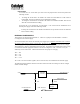
As you can see, there will be conflict in case the external supply is connected while the jumper is still in place. This circuit is repeated for each of the 4 voltages, with the exception of the Auxiliary circuit. If you are using external power supplies do not forget to connect the Ground (GND) signals between the system and the supply.
LED TABLE LED Purpose +5V Present +12V Present -12V Present VIO Present +3.3V Present +5V Problem +12V Problem -12V Problem +3.3V Problem PCIAX532/PCIAX332 D12 D11 D10 D18 D13 D16 D15 D9 D14 CPCI-64 D15 D4 D3 D9 D5 D7 D11 D2 D6 LEDs There are two sets of LED on the board, green and red. Each LED has a label which voltage it represents. The green LED, when lit, indicates presence of the corresponding voltage. The red LED, when lit, represent a short on the corresponding voltage.
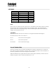
SPECIFICATION: Bus: PCIAX532 & PCIAX332 PCIAX-532, 32-bit PCI, 5V key and universal. PCIAX-332, 32-bit PCI, 3V key and universal. Voltages: Input requirement Inputs +5V at 200 mA, +/- 12V at 50 mA. From PC bus or the external input, configurable by jumpers per voltage. (For Rev B boards only) Output Ratings +5V, Jumper selectable to 5 Amp or 1 Amp limit, higher than 5 Amp current limit can be accommodated per user request. +3.3V @ 2.5 Amps if on-board regulator is used. +3.
SPECIFICATION: CPCI-64 Bus: CompactPCI 32 or 64 bit, system slot or adapter card. Voltages: Input requirement Inputs for UUT +5V at 200 ma, +/- 12V at 50 mA. From PC bus or the external input, configurable jumpers per voltage. Output Ratings Output Voltage Drop Propagation Delay: ON-OFF Controls: Outputs: J3 JTA-E Mechanical Dimensions: Height Width +5V, Jumper selectable to 5 Amp or 1 Amp limit. +3.3V @ 2.5 Amps. +VIO @ 1 Amp. +/- 12V @ 1 Amp. 40 millivolts drop for every 1 Amp drawn for +5V, +3.
BOARD LAYOUT, PCIAX 11
BOARD LAYOUT, CPCI-64 12