
Owner manual


8
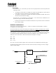
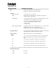
LED TABLE
LED Pur
p
ose PCIAX532/PCIAX332 CPCI-64
+5V Present D12 D15
+12V Present D11 D4
-12V Present D10 D3
VIO Present D18 D9
+3.3V Present D13 D5
+5V Problem D16 D7
+12V Problem D15 D11
-12V Problem D9 D2
+3.3V Problem D14 D6
LEDs
There are two sets of LED on the board, green and red. Each LED has a label which voltage it represents.
The green LED, when lit, indicates presence of the corresponding voltage. The red LED, when lit,
represent a short on the corresponding voltage. Please note that the green LEDs do not indicate if the
voltage is at the expected level or not.
3.3V INPUT
These Active Extender cards have an on-board 3.3 Volt regulator (PCIAX Rev B and higher).
JP7 selects the source of the 3.3V to the UUT.
JP7 1-2 3.3V from the on-board regulator.
JP7 2-3 3.3V from the system bus.
JP7 no shunts 3.3V from the external supply.
5V=>3V TRANSLATION
These Active Extender cards are capable of translating the incoming 5-Volt signals to 3.3 Volts for the
UUT without any timing degradation. Therefore cards or components needing a 3-Volt environment can
be tested or operated on a 5-Volt system using these extender cards.
With JP3 installed the UUT signals will be the same as the bus signals, most likely 5V. When JP3 is not
installed, the signals to the UUT will be translated down to 3.3V.