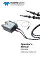
Operator’s Manual DXC100A Differential Probe Pair
© 2013 Teledyne LeCroy, Inc. All rights reserved. Unauthorized duplication of Teledyne LeCroy documentation materials other than for internal sales and distribution purposes is strictly prohibited. However, clients are encouraged to distribute and duplicate Teledyne LeCroy documentation for their own internal educational purposes. WaveSurfer, WaveRunner, and Teledyne LeCroy are registered trademarks of Teledyne LeCroy, Inc. Windows is a registered trademark of Microsoft Corporation.
DXC100A Differential Probe Pair Safety Instructions This section contains instructions that must be observed to keep this oscilloscope accessory operating in a correct and safe condition. You are required to follow generally accepted safety procedures in addition to the precautions specified in this section. The overall safety of any system incorporating this accessory is the responsibility of the assembler of the system.
Operator’s Manual Keep product surfaces clean and dry. Do not submerge probe. Clean with a water- or alcohol-moistened cloth. Do not use harsh or abrasive cleansers. Be careful with sharp tips. Tips may cause bodily injury if not handled properly. Do not operate with suspected failures. Do not use if any part is damaged. Cease operation immediately and sequester the probe from inadvertent use. Operating Environment The accessory is intended for indoor use and should be operated in a clean, dry environment.
DXC100A Differential Probe Pair A Word about Differential Amplifiers and Probes When using a differential amplifier it is very important to understand the role probes play in the overall measurement system performance. Probes not only make attachment to the circuit under test more convenient, 10X and 100X attenuating probes also extend the common mode range of the differential amplifier. For example, the DA1855A amplifier has a common mode range of ± 15.
Operator’s Manual Probe Grounding The DXC100A Probe Pair is supplied with accessories allowing for three probe ground connection methods. In most cases, when the common mode portion of the signal consists mainly of low frequencies (1 MHz and below), the probe ground leads should not be connected to the ground of the circuit under test. Instead, they should be connected to each other to minimize the effects of ground loop currents.
DXC100A Differential Probe Pair Once you are accustomed to making these adjustments, they become quick and easy. Part 2 can be attempted when high slew rates (>1V/ns) are encountered, and/or when high frequency (time constraints less than 20ns and frequencies greater than 1MHz) CMRR is especially important. Note: Do not change any of the adjustments associated with the +INPUT. Doing so requires checking the changed adjustment, and perhaps doing the entire Full Calibration Procedure.
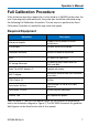
Operator’s Manual Full Calibration Procedure If the probe pair has been repaired or is to be used on a DA1855A other than the one it was originally calibrated with, the probe pair should be calibrated using the following Full Calibration Procedure. The last step is to perform the Short Calibration Procedure as needed for high slew rate signals.
DXC100A Differential Probe Pair 1. DA1855A and Oscilloscope Setup Follow the sequence shown in the previous Short Calibration Procedure topic to set up the DA1855A amplifier with your oscilloscope. a. Remove the probe’s bottom cover and attach the probe to the DA1855A. b. Turn the entire DA1855A and probe to gain access to the adjustments. NOTE: Do not attach the probe upside down and then reverse the probes after they are compensated.
Operator’s Manual DA1855A has no probe coding input, and the wire is not used. Skip to Step 2. It is important to use the right hardware to connect the probes to the test signals. In all cases, the BNC to probe tip adapters are helpful. For the high frequency adjustments, they are required. CMRR (common mode rejection ratio) adjustments should be done with both probes connected to a BNC T (two female BNC and one male BNC connected together without any matching resistors).
DXC100A Differential Probe Pair b. Adjust R6 (-X10 DC) to bring the DA1855A output to center screen (0 volts) on the oscilloscope. This is a very critical adjustment, and it is desirable to disconnect both probes from the source simultaneously (by removing the BNC T) and observe that the trace stays within 0.25 div (60,000:1 CMRR) between the two conditions. 4. +Input X100 DC Attenuation a. Continuing from the previous step, set the probe to the 100X position. b. Set the voltage source to 300 volts. c.
Operator’s Manual 6. +Input X10 LF Compensation NOTE: Low frequency compensation of the DXC100A probe attached to the +Input is done by observing a small portion of the large amplitude step. With this magnification, the waveform shows considerable deviation from flat. What is important is that the front (1μs) and rear (about 10ms) of the waveform are at the same level. a. Set the probe to the 10X position. b. Set the oscilloscope to 10mV/div and 10μs/div. c.
DXC100A Differential Probe Pair 8. +Input X10 HF Transient Response a. Press the –Input Off button. b. Set the BW Limit to Full. c. Press the X1 Gain button. d. Set the oscilloscope to 20mV/div. e. Connect the +probe to the pulse generator’s fast rise output using a 50 Ohm termination and the BNC to probe tip adaptor. f. Press the VDiff button to enable VDiff mode. g. Position the trace 2½ divisions above the centerline using the PVG (00.500). h. Press the +Input DC button. i.
Operator’s Manual 10. +Input X100 LF Compensation NOTE: Low frequency compensation of the DXC100A probe attached to the +Input is done by observing a small portion of a large amplitude step. For the 100X probe attenuation, the oscilloscope transient response plays an important part in determining the correct LF compensation adjustment. The oscilloscope response should be measured at this point and recorded as a reference waveform.
DXC100A Differential Probe Pair 11. X100 LF CMRR a. Continuing from the previous step, disconnect the probe from the pulse generator. b. Connect both probes to the pulse generator’s high amplitude output using a 50 Ohm or (preferably) 75 Ohm termination, the BNC T, and two BNC to probe tip adapters. c. Press the –Input DC button. d. Adjust C18 (-X100 LF1) and C12 (-X100 LF2) for minimum displayed signal. Ignoring the first 1μs (0.1div), the residual displayed amplitude should be less than 2mV (0.
Operator’s Manual d. Set the oscilloscope to 5mV/div. e. Adjust R18 (-X100 HF1) for minimum displayed signal. The residual displayed amplitude should be less than 8mV peak to peak (1.6 div). f. Now, replace probe cover. Replacing the probe cover disturbs the X10 LF and X100 LF compensations for CMRR very slightly. These fine adjustments need to be made now. 14. Final Adjustments and Notes a. Set the BW Limit to 20MHz. b. Set the oscilloscope to 10mV/div and 10μs/div, and the probe attenuation to 10X. c.
DXC100A Differential Probe Pair When the +probe has been properly adjusted it should be used as a reference. CMRR adjustments made to the probe in the future should be done to the – probe. At this point, do not change any of the +Input X10 or +Input X100 Adjustments, as doing so may require repeating the entire probe calibration procedure.
Operator’s Manual Figure 2, The DXC100A Schematic 922259-00 Rev A 17
DXC100A Differential Probe Pair Certifications This section contains the instrument’s Electromagnetic Compatibility (EMC), Safety and Environmental certifications. EMC Compliance EC Declaration of Conformity - EMC The probe meets intent of EC Directive 2004/108/EC for Electromagnetic Compatibility.
Operator’s Manual Australia & New Zealand Declaration of Conformity—EMC Probe complies with the EMC provision of the Radio Communications Act per the following standards, in accordance with requirements imposed by Australian Communication and Media Authority (ACMA): CISPR 11:2003 Radiated and Conducted Emissions, Group 1, Class A, in accordance with EN61326-1:2006 and EN61326-2-1:2006. Australia / New Zealand Contacts: Vicom Australia Ltd.
DXC100A Differential Probe Pair Contact Teledyne LeCroy Teledyne LeCroy Service Centers United States and Canada World Wide Corporate Office Teledyne LeCroy Corporation 700 Chestnut Ridge Road Chestnut Ridge, NY, 10977-6499, USA Ph: 800-553-2769 / 845-425-2000 FAX: 845-578-5985 teledynelecroy.com Support: contact.corp@teledynelecroy.com Sales: customersupport@teledynelecroy.