
User Manual

Operator’s Manual
922259-00 Rev A 15
d. Set the oscilloscope to 5mV/div.
e. Adjust R18 (-X100 HF1) for minimum displayed signal. The residual
displayed amplitude should be less than 8mV peak to peak (1.6 div).
f. Now, replace probe cover. Replacing the probe cover disturbs the X10 LF
and X100 LF compensations for CMRR very slightly. These fine
adjustments need to be made now.
14. Final Adjustments and Notes
a. Set the BW Limit to 20MHz.
b. Set the oscilloscope to 10mV/div and 10μs/div, and the probe
attenuation to 10X.
c. Terminate the pulse generator’s high amplitude output in 50 or
(preferably) 75 Ohms, producing approximately a 5 to 8 volt step.
d. Connect both probes to the pulse generator’s high amplitude output
using the BNC T and two probe tips to BNC adaptors.
e. Press the X1 Gain button.
f. Press the +Input and –Input DC buttons.
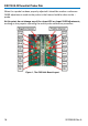
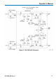
g. Adjust C8 (-X10 LF) capacitor for a minimum amplitude display. Ignoring
the first 1μs, the residual displayed amplitude should be less than 5mV
peak to peak.
h. Continuing from the previous step now set the probe attenuation to
100X.
i. Adjust C18 (-X100 LF1) capacitor for a minimum amplitude display.
NOTE: Pulse generators such as the Tektronix PG506 (that do not have a high
enough slew rate) may be encountered in some measurement situations.
Therefore it is reasonable to make minor adjustments to the –probe
compensation to improve the CMRR using a specific source. Do this by
connecting both probes to a suitable test point in the circuit under test and
adjusting the C8 (–X10 LF), R2 (-X10 HF1), R8 (-X10 HF2) or C18 (–X100 LF1), and
R18 (-X100 HF1) as needed. This is the same as performing the DXC100A Probe
Short Calibration Procedure.