Operator's Manual ET-PMT Software
Electrical Telecom Pulse Mask Test Software Operator's Manual © 2013 Teledyne LeCroy, Inc. All rights reserved. Unauthorized duplication of Teledyne LeCroy documentation materials other than for internal sales and distribution purposes is strictly prohibited. However, clients are encouraged to distribute and duplicate Teledyne LeCroy documentation for their own internal educational purposes. Electrical Telecom Pulse Mask Test and Teledyne LeCroy are trademarks of Teledyne LeCroy, Inc.
Operator's Manual Contents Introduction Standards Supported Text Fixtures 2 2 3 Set Up Standard Mask Test 4 Add Measurements to Mask Test 6 Create Custom Mask Test Mask Definition Properties 7 7 923136 Rev A 1
Electrical Telecom Pulse Mask Test Software Introduction ET-PMT is a software package that measures pulse mask compliance of electrical telecommunications signals. Pulse mask testing consists of acquiring the given signal in an oscilloscope and comparing the voltage vs. time waveform to a standard mask. The mask defines regions in V,t space where a compliant signal must remain.
Operator's Manual Text Fixtures Telecommunications signals require specific load impedance for compliance testing to be accurate. The twisted pair standards require 100 Ohm and 120 Ohm terminations, and the other standards require 75 Ohm terminations. A set of adapters (test fixtures) for this purpose is available from Teledyne LeCroy (part number TF-ET). NOTE: These adapters require an additional LPA-BNC-ProLink adapter if they are being used with a WaveMaster, LabMaster, or SDA.
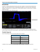
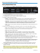
Electrical Telecom Pulse Mask Test Software Set Up Standard Mask Test 1. From the menu bar, choose Analysis > Electrical Telecom to display the Electrical Telecom setup dialog. 2. Touch Telecom Standard and select the desired standard. This will automatically set the requisite bit rate, mask, and pulse isolation criteria for the measurement. 3. Touch Source and select the channel to which the signal is connected. 4.
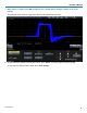
Operator's Manual 7. When setup is complete, press Run to begin the test. The Run button changes to Pause as the test is running. The example below shows a stopped test with a failure identified (red circle). 8. To pause the test without resetting the counter, press Pause. Press Run again to resume testing. To stop the test and reset the counter, press Clear Sweeps.
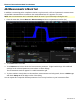
Electrical Telecom Pulse Mask Test Software Add Measurements to Mask Test In addition to measuring pulse compliance relative to a given mask, a full set of parametric measurements are available. Measurements are made on the masked waveform as it appears on screen. NOTE: Some measurements are incremental and will be reset if you Clear Sweeps during the test. 1. From the menu bar, choose Measure > Measure Setup and choose a parameter location (Px). 2. Touch Source and select ET. 3.
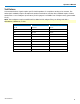
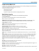
Operator's Manual Create Custom Mask Test In addition to the standard pulse masks, custom masks can be created by modifying the mask definition file, D:\Masks\PulseMasksProp.mdb, using Microsoft Access. A complete mask definition includes: l Mask definition properties l Pulse alignment criteria l Acquisition settings such as waveform averaging and persistence Mask Definition Properties Enter values for the properties indicated below in the PulseMasksProp.
Electrical Telecom Pulse Mask Test Software Gate Start—The limit in DIV in the waveform data at which the mask test is started. Gate Stop—The limit in DIV in the waveform data at which the mask test is stopped. This property and the one above it allow you to perform mask testing on specific pulses within a longer, more complex waveform. Mask Data (optional) -- Hyperlink to an Access table that contains the mask data.