
Owner manual


Operator's Manual
Control Loop Analysis
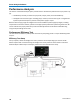
Control Loop Analysis Preliminary Setup
Switched-mode power conversion circuits use some method of transferring energy from an unregulated
source to regulated outputs on a cycle-by-cycle basis. Output regulation is achieved by modulating the
amount of energy transferred in each cycle, the most common method being Pulse Width Modulation
(PWM). Other methods (such as frequency modulation) are also used.
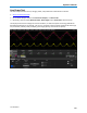
Control Loop analysis provides you with tools to view the information contained in the control circuit’s
modulated signals. It does this by taking the time (duty cycle or width) information in the modulated sig-
nal that is normally displayed on the horizontal axis, along with elapsed time, and displays it on the ver-
tical axis.
As the number of pulses per division increases, the display of their individual widths forms a “waveform”
that represents the change in pulse width (or other characteristic) as a function of elapsed time. This
“waveform” can be used to gain valuable information about the power supply’s response to various
events, such as load change (step response) or its soft-start performance.
921326 Rev B
19