QPHY-10GBASE-T (Tx and RL Tests) Operator’s Manual Revision A – April, 2014 Relating to the following release versions: Software Version Rev. 7.4.x.x Script 10GBASET.IRT, 10GBASET_RL.IRT Style Sheet Rev. 1.
700 Chestnut Ridge Road Chestnut Ridge, NY, 10977-6499 Tel: (845) 425-2000, Fax: (845) 578 5985 teledynelecroy.com © 2014 Teledyne LeCroy, Inc. All rights reserved. Teledyne LeCroy and other product or brand names are trademarks or requested trademarks of their respective holders. Information in this publication supersedes all earlier versions. Specifications are subject to change without notice.
QPHY-10GBASE-T Operator’s Manual Table of Contents Introduction ...............................................................................................................................1 About QualiPHY ............................................................................................................................................ 1 About QPHY-10GBASE-T Option .................................................................................................................
Table of Figures Figure 1 - QualiPHY framework dialog and Standard selection menu. ................................................. 5 Figure 2 - The Test Report summary page. .............................................................................................. 8 Figure 3 - Variable Setup tab. ................................................................................................................... 10 Figure 4 - Limits Manager dialog. .......................................................
QPHY-10GBASE-T Operator’s Manual Introduction About QualiPHY QualiPHY is a highly automated compliance test software meant to help you develop and validate the PHY (physical-electrical) layer of a device, in accordance with the official documents published by the applicable standards organizations and special interest groups (SIGs). You can additionally set custom variables and limits to test compliance to internal standards.
Required Host Computer System Usually, the oscilloscope is the host computer for the QualiPHY software, and all models that meet the acquisition requirements will also meet the host system requirements.
QPHY-10GBASE-T Operator’s Manual Installation and Setup QualiPHY is a Windows-based application that can be configured with one or more serial data compliance components. Each compliance component is purchased as a software option. Install Base Application Download the latest version of the QualiPHY software from: teledynelecroy.
Set Up Remote Control QualiPHY software can be executed from a remote host computer, controlling the oscilloscope through a LAN Connection. To set up remote control: • The oscilloscope must be connected to a LAN and assigned an IP address (fixed or dynamic). • The host computer must be on the same LAN as the oscilloscope. Note: LXI, GPIB, LSIB, and USBTMC remote control is available for some model instruments.
QPHY-10GBASE-T Operator’s Manual Using QualiPHY This section provides an overview of the QualiPHY user interface and general procedures. For detailed information about the QPHY-10GBASE-T software option, see QPHY-10GBASE-T Tx Testing and QPHY-10GBASE-T RL Testing. Accessing the Software Once QualiPHY is installed and activated, it can be accessed from the oscilloscope menu bar by choosing Analysis > QualiPHY, or by double-clicking the QualiPHY desktop icon on a remote computer.
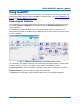
General Setup The first sub-dialog contains general system settings. These remain in effect for each session, regardless of Standard, until changed. Connection tab Shows IP Address of the test oscilloscope (local host 127.0.0.1 if QualiPHY is run from the oscilloscope). The Scope Selector allows you to choose the oscilloscope used for testing when several are connected to the QualiPHY installation. See Set Up Remote Control for details.
QPHY-10GBASE-T Operator’s Manual QualiPHY Test Process Once general system settings are in place, these are the steps for running test sessions. Set Up Test Session 1. Connect the oscilloscope to the DUT. 2. Access the QualiPHY software to display the framework dialog. 3. If running QualiPHY remotely, click General Setup and open the Scope Selector to select the correct oscilloscope connection. 4.
Run Reports The QualiPHY software automates report generation. On the framework dialog, go to General Setup > Report to pre-configure reporting behavior. You can also manually launch the Report Generator from the framework dialog once a test is run. The Report Generator offers the same selections as the Report tab, only applied to each report individually, rather than as a system setting. This enables you to save reports for each test session, rather than overwrite the generic report file.
QPHY-10GBASE-T Operator’s Manual Customizing QualiPHY The pre-loaded configurations cannot be modified. However, you can create your own test configurations by copying one of the standard test configurations and modifying it. Copy Configuration 1. Access the QualiPHY framework dialog and select a Standard. 2. Click Edit/View Configuration and select the configuration upon which to base the new configuration. This can be a pre-loaded configuration or another copy. 3.
Edit Variables The Variable Setup tab contains a list of test variables. To modify a variable: 1. Select the variable on the Variable Setup tab, then click Edit Variable. (You can also choose to Reset to Default at any time.) 2. The conditions of this variable appear on a pop-up. Choose the new condition to apply. Figure 3 - Variable Setup tab.
QPHY-10GBASE-T Operator’s Manual Edit Test Limits The Limits tab shows the Limit Set currently associated with the configuration. Any limit set can be associated with a custom configuration by selecting it in this field. The Limits Manager shows the settings for every test limit in a limit set. Those in the default set are the limits defined by the standard. To create a custom limit set: 1. On the Limits tab, click Limits Manager. 2. With the default set selected, click Copy Set and enter a name.
X-Replay Mode The X-Replay mode window is an advanced (“developer”) view of QualiPHY. The tree in the upper-left frame enables you to navigate to processes in the 10GBASE-T test script, in case you need to review the code, which appears in the upper-right frame. Two other particularly useful features are: • A list of recent test sessions in the lower-left frame.
QPHY-10GBASE-T Operator’s Manual QPHY-10GBASE-T Tx Testing This section covers the transmitter compliance tests. Test Preparation Before beginning any test or data acquisition, the oscilloscope should be warmed for at least 20 minutes. Calibration is automatic under software control and no manual calibration is required. This procedure will be run again if the temperature of the oscilloscope changes by more than a few degrees.
QPHY-10GBASE-T Tx Test Descriptions These are the standard 10GBASE-T transmitter compliance tests. Test 1 - Maximum Output Droop The purpose of this test is to verify that the magnitude of the transmitter output droop is within the conformance limits as defined in section 55.5.3.1 of the IEEE 802.3-2008 specification. This test uses Test Mode 6.
QPHY-10GBASE-T Operator’s Manual Figure 6 – Maximum Output Droop Test Results Shown on this screen: • F1 = C1-C2 • P1 = Lvl10ns, = Level@X where X is T=10ns after the falling edge • P2 = Lvl90ns, = Level@X where X is T=90ns after the falling edge • P3 = 100* (P1-P2) / P1, using the processing web 923663 Rev A 15
Test 2 - Transmitter Linearity The purpose of this test is to verify that the SFDR is within the conformance limits as defined in section 55.5.3.2 of the IEEE 802.3-2008 specification. This test uses Test Mode 4. WHAT IS MEASURED For each of the dual-tone options in Test Mode 4, the averaged spectrum of the differential signal C1-C2 is measured in order to determine the spurious-free dynamic range (SFDR). QualiPHY will instruct you to setup each dual-tone setting.
QPHY-10GBASE-T Operator’s Manual Test 3 - Transmitter Timing Jitter (Master) The purpose of this test is to verify that the RMS period jitter of the MASTER PHY transmitter is within the conformance limits as defined in section 55.5.3.3 of the IEEE 802.3-2008 specification. This test uses Test Mode 2. WHAT IS MEASURED The sdev of the period of differential clock C1-C2 is measured, while filtering the difference of C1 and C2 with an IIR that is defined by the test specification.
Test 4 - Transmitter Clock Frequency The purpose of this test is to verify that the symbol transmission rate of the MASTER PHY transmitter is within the conformance limits as defined in section 55.5.3.5 of the IEEE 802.32008 specification. This test uses Test Mode 2. WHAT IS MEASURED The frequency of the differential clock signal C1-C2 is measured. TEST METHODOLOGY Test Mode 2 outputs a 200MHz clock. The oscilloscope finds the scale, and acquires a sweep at 100us/div with 20MS record length.
QPHY-10GBASE-T Operator’s Manual Test 5 - Transmitter Power Spectral Density The purpose of this test is to verify that the power spectral density of the transmitter is within the conformance limits as defined in section 55.5.3.4 of the IEEE 802.3-2008 specification. This test uses Test Mode 5. WHAT IS MEASURED The power spectral density is measured by taking the FFT of the ERES of the differential signal C1-C2 TEST METHODOLOGY The signal output using Test Mode 5 is acquired by the oscilloscope.
Test 6 - Transmitter Power Level The purpose of this test is to verify that the power level of the transmitter is within the conformance limits as defined in section 55.5.3.4 of the IEEE 802.3-2008 specification. This test uses Test Mode 5. WHAT IS MEASURED The area of the averaged FFT of the differential signal C1-C2 is measured. TEST METHODOLOGY The Test Mode 5 signal is analyzed by taking an averaged FFT of the differential signal C1-C2. At least 2000 waveforms are acquired to form the averaged FFT.
QPHY-10GBASE-T Operator’s Manual Test 7 - Transmitter Timing Jitter (SLAVE) The purpose of this test is to verify that the RMS period jitter of the SLAVE PHY transmitter is within the conformance limits defined in section 55.5.3.3 of the IEEE 802.3-2008 specification. This test uses Test Mode 1 for the MASTER PHY and Test Mode 3 for the SLAVE PHY.
QPHY-10GBASE-T Tx Variables There is one variable that can be set for QPHY-10GBASE-T Tx testing: PAIRS TO TEST Specify whether to test a single pair (A, B, C or D), or all pairs. QPHY-10GBASE-T Limit Sets The default installation of QPHY-10GBASE-T Tx contains only one limit set, called “Default.” In this script, limits are only used to convey Unit labels. The actual limits for each value tested are encoded in or computed by the script and cannot be changed.
QPHY-10GBASE-T Operator’s Manual QPHY-10GBASE-T Return Loss Testing Test Preparation Before beginning any test or data acquisition, the SPARQ network analyzer should be warmed for at least 20 minutes. Calibration is automatic under software control and no manual calibration is required. This procedure will be run again if the temperature of the oscilloscope changes by more than a few degrees. Required Equipment • SPARQ Series Signal Integrity Network Analyzer (e.g.
QPHY-10GBASE-T RL Test Configurations All Tests There is only one configuration to choose from. This configuration enables users to perform the fixture calibration and MDI return loss test. QualiPHY will indicate which ports to connect to on the TF-10GBASE-T fixture (e.g. A+/A-). QPHY-10GBASE-T RL Tests PreTest – Fixture Calibration The purpose of this is to perform a second tier calibration to adjust the reference plane for the impedance measurements.
QPHY-10GBASE-T Operator’s Manual DEFAULT PASS CONDITION: The portion of the measured impedance profile that is specified in the standard (0 – 500MHz) is compared to a limit trace (math function F2). If any points in the profile are above the limit trace, the test fails. To make this determination, the measured impedance profile is subtracted from the limit trace in math trace F3 (not displayed), and the minimum of the difference is calculated in parameter P1. If P1>0, the test passes.
QPHY-10GBASE-T RL Variables FIXTURE DE-EMBEDDING CALIBRATION FILE A Specify the full path that points to the L12T file used for de-embedding the fixture Pair A with the second tier calibration method. FIXTURE DE-EMBEDDING CALIBRATION FILE B Specify the full path that points to the L12T file used for de-embedding the fixture Pair B with the second tier calibration method.
QPHY-10GBASE-T Operator’s Manual Manual Deskewing Procedures This section is only applicable to the oscilloscope and the cables connecting to the oscilloscope channels. Note that the cables connecting the PeRT3 to the fixture or to the DUT must be phase matched within a tight tolerance because the PeRT, like any generator, does not have the capability to compensate for mismatched cables connected to its outputs.
• Trigger i. Configure to Source to be FastEdge. ii. Set the Slope to Positive. • Parameter Measurements: i. Set the source for P1 to CX and the measure to Delay. ii. Set the source for P2 to CY and the measure to Delay. iii. Set the source for P3 to M1 and the measure to Delay. 3. Set the display to Single Grid. • Click Display Single Grid. 4. Using the appropriate adapter, connect Channel X to the Fast Edge Output of the oscilloscope. 5.
QPHY-10GBASE-T Operator’s Manual 10. Save Channel X to M1. • Click File Save Waveform. • Set Save To Memory. • Set the Source to CX. • Set the Destination to M1. • Click Save Now. 11. Disconnect Channel X from the Fast Edge Output and connect Channel Y to the Fast Edge Output. 12. Press the Clear Sweeps button on the front panel to reset the averaging. 13. Allow multiple acquisitions to occur until the waveform is stable on the screen. 14.
Cable Deskewing Without Using the Fast Edge Output The following procedure demonstrates how to manually deskew two oscilloscope channels and cables using the differential data signal, with no need for any T connector or adapters. This can be done once the temperature of the oscilloscope is stable. The oscilloscope must be warmed up for at least a half-hour before proceeding. This procedure should be run again if the temperature of the oscilloscope changes by more than a few degrees. 1.
QPHY-10GBASE-T Operator’s Manual In the previous procedure, we used the default setup of the Skew parameter (which is detecting positive edges on both signals at 50%). We also inverted C2 in order to make C1 and C2 both have positive edges at the same time. Alternately, we clearly could have not inverted C2 and instead selected the Skew clock 2 tab in the P1 parameter menu and set the oscilloscope to look for negative edges on the second input (C2).