
Manual

QPHY-10GBASE-T Operator’s Manual
Test 3 - Transmitter Timing Jitter (Master)
The purpose of this test is to verify that the RMS period jitter of the MASTER PHY transmitter is
within the conformance limits as defined in section 55.5.3.3 of the IEEE 802.3-2008
specification. This test uses Test Mode 2.
W
HAT IS MEASURED
The sdev of the period of differential clock C1-C2 is measured, while filtering the difference of
C1 and C2 with an IIR that is defined by the test specification.
T
EST METHODOLOGY
Test Mode 2 outputs a 200MHz clock signal. The oscilloscope finds the scale, and acquires a
sweep at 2us/div with 400kS. The waveform includes ~4000 cycles of the clock. The IIR filter
(polynomial defined in D:\Applications\EthernetBPF.txt) filters the waveform, bringing the
number of cycles down to ~3900. The period@level measurement is applied to the filtered
waveform, and the sdev of the measurement is the jitter result. This is compared to the
PeriodJitter value in the limits table to determine if the test passes.
D
EFAULT PASS CONDITION:
The test passes if the result is less than 5.5 ps.
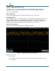
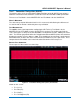
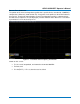
Figure 8 – Transmitter Timing Jitter (Master) Test Results
Shown on this screen:
• F1 = C1-C2
• F2 = Filter(F1)
• F3 = Hist(P1)
• P1 = Period@Level(F2)
923663 Rev A 17