
Manual

Test 4 - Transmitter Clock Frequency
The purpose of this test is to verify that the symbol transmission rate of the MASTER PHY
transmitter is within the conformance limits as defined in section 55.5.3.5 of the IEEE 802.3-
2008 specification.
This test uses Test Mode 2.
W
HAT IS MEASURED
The frequency of the differential clock signal C1-C2 is measured.
T
EST METHODOLOGY
Test Mode 2 outputs a 200MHz clock. The oscilloscope finds the scale, and acquires a sweep at
100us/div with 20MS record length. The bitrate measurement is used to characterize the
frequency of the clock. (Bitrate returns a frequency when the signal is a clock). The value
measured, times four, is compared to the SymbolRate value in the limits table to determine if the
test passes.
D
EFAULT PASS CONDITION:
The test passes if the result is within 50ppm (+/- 40 kHz)
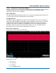
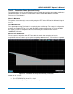
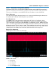
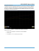
Figure 9 – Transmitter Clock Frequency Test Results
Shown on this screen:
• F1 = C1-C2
• P1 = Bitrate(F1)
18 923663 Rev A