
Manual

QPHY-10GBASE-T Operator’s Manual
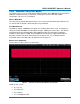
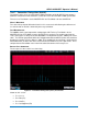
DEFAULT PASS CONDITION:
The portion of the measured impedance profile that is specified in the standard (0 – 500MHz) is
compared to a limit trace (math function F2). If any points in the profile are above the limit trace,
the test fails. To make this determination, the measured impedance profile is subtracted from
the limit trace in math trace F3 (not displayed), and the minimum of the difference is calculated
in parameter P1. If P1>0, the test passes.
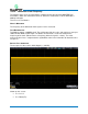
Figure 13 – Transmitter Clock Frequency Test Results
Shown on this screen:
• F1: S11 result, interpolated, and zoomed to show 0 to 500 MHz
• F2: limit curve
• P1: min(F2-F1). If P1 < 0, then the test has failed.
923663 Rev A 25