
Owner manual


QPHY-ENET Software Option
QPHY-ENET Operator’s Manual Rev G
49
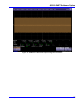
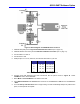
Figure 37. Block diagram of TF-ENET-B fixture section D
1. Calibrate data path (see the
X
Signal Path Calibration Procedure
X
topic on page
X
74
X
).
2. Calibrate disturber sine wave (see the
X
Disturber Calibration Procedure
X
topic on page
X
77
X
).
3. Connect AWG to J3 and J4.
4. Connect DUT to J68.
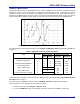
5. Install jumpers on J17/J19, J99/J100, J91/J92 and select Pair for your test.
Table 5. Section D test pair jumper configurations
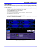
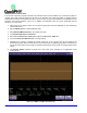
6. Transmit signal with disturbing sine wave should look like the picture shown in
X
Figure 41
X
. Select
1000Base-T under “Select Standard.”
7. Select Mode 1 Transmit Wform in the “Select Test” field.
8. Check Differential Data on 2 Channels box and enter C2 for Source for + Data and C3 for Source for
– Data.
9. Touch the Set Up and Start Test button to begin testing. The test automatically attempts to position each
pulse, so that it passes its template.
Pair Install Remove
A J39, J40 J61, J60, J62
B J43, J44 J59, J60, J62
C J41, J42 J59, J61, J62
D J45, J46 J59, J61, J60