
Owner manual


54
QPHY-ENET Operator’s Manual Rev G
Mode 1 and Mode 4 without Disturbing Signal
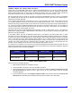
These tests are performed on a physical interface transmitting the mode 1 and mode 4 waveform. Test section G
is used to perform the peak voltage and template tests. When a disturbing signal is not used, the measurement
should be made with the device terminated by a 100 Ω resistive load. The test procedure is identical to
X
1000Base-T Peak Differential Voltage, Droop, Template - Mode 1 with Disturbing Signal
X
(page
X
48
X
) except
for not changing jumpers but changing a connection of SMA cable location in section G (
X
Figure 43
X
), when each
pair is measured, according to the table shown in
X
Table 6
X
. Mode 1 test uses Mode 1 signal and Mode 4 test uses
Mode 4 signal for the tests.
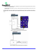
Table 6. Section G connector configuration and pair
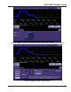
Figure 43. Fixture setup for Mode 1 and Mode 4 test without Disturbing Signal
1. On the oscilloscope’s Ethernet menu, Disturber present checkbox MUST be unchecked.
Figure 44. Menu setting for making the measurements without disturber present
Pair CH2 CH3
A J51 J30
B J52 J31
C J32 J53
D J54 J33