USB3.0 Serial Data Operator’s Manual 917719 Revision A – December, 2009 Relating to the Following Release Versions: Software Option Rev. 6.0 USB3 Script Rev. 1.0 Style Sheet Rev. 1.
LeCroy Corporation 700 Chestnut Ridge Road Chestnut Ridge, NY, 10977-6499 Tel: (845) 578-6020, Fax: (845) 578 5985 Internet: www.lecroy.com © 2009 by LeCroy Corporation. All rights reserved. LeCroy and other product or brand names are trademarks or requested trad emarks of their respective holders. Information in this publication supersedes all earlier versions. Specifications are subject to change without notice.
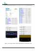
QPHY-USB3-Tx-Rx Software Option TABLE OF CONTENTS INTRODUCTION ...................................................................................................................................... 6 Compatibility...................................................................................................................................................6 Additional Options Equipment A vailable from LeCroy ........................................................................................
Test 1.4 AC and DC Common Mode Voltage Tests ..........................................................................................34 Test 1.5 Differential Voltage & De-emphasis Test ............................................................................................34 Receiver Test Calibration...............................................................................................................................36 Test 2.1 Jitter Tolerance Test ............................................
QPHY-USB3-Tx-Rx Software Option FIGURES Figure Figure Figure Figure Figure Figure Figure Figure Figure Figure Figure Figure Figure Figure Figure Figure Figure Figure Figure Figure Figure Figure Figure Figure Figure Figure Figure Figure Figure Figure Figure Figure Figure Figure Figure Figure Figure Figure Figure 1 - TF-US B3 Fixture Set .....................................................................................................................6 2. Report menu in QualiPHY General Setup.............
INTRODUCTION QPHY-USB3-Tx -Rx is a software package designed to capture, analyze, and report measurements in conformance wit h SuperSpeed USB electrical specification standard. A copy of the specification can be found at www.usb. org. Compatibility QPHY-USB3-Tx -Rx is a software option compatible with the following LeCroy X-Stream oscilloscopes: WM813Zi, SDA813Zi, DDA813Zi (4x40 GS/s, 2x80GS/s) and higher bandwidth equivalents. SDA II and Eye Doctor II software is required.
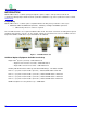
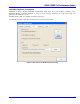
QPHY-USB3-Tx-Rx Software Option QualiPHY Compliance Test Platform QualiP HY is LeCroy’s unique compliance test framework which leads the user through the complianc e tests. QualiP HY displays connection diagrams to ensure tests run properly, automates the oscilloscope setup, and generates full compliance reports. QualiP HY makes USB 3.0 compliance testing easy and fast. The QualiPHY soft ware application automates the test and report generation. Figure 2.
See the QualiPHY Operator’s Manual for more information on how to use the QualiPHY framework. Figure 3.
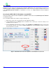
QPHY-USB3-Tx-Rx Software Option Oscilloscope Option Key Installation An option key must be purchased to enable the QP HY-USB3 option. Call LeCroy Customer Support to place an order and receive the code. Enter the key and enable the purchased option as follows: 1. From the oscilloscope menu select Utilities Utilities Setup... 2. Select the Options tab and click the Add Key button. 3. Enter the Key Code using the on-screen keyboard. 4. Restart the oscilloscope to activate the option after installation.
QualiP HY tests the oscilloscope connection after clicking the Start button. The system prompts you if there is a connection problem. QualiPHY’s Scope Selector function can also be used to verify the connection. Please refer to the QualiPHY Operator’s Manual for explanations on how to us e Scope Selector and other QualiP HY functions. Accessing the QPHY-USB3-Tx-Rx Software using QualiPHY This topic provides a basic overview of QualiP HY’s capabilities.
QPHY-USB3-Tx-Rx Software Option 4. Click the Configuration button in the QualiP HY main menu. 5. Select a configuration from the pop-up menu. For addition information, pleas e refer to the QPHY-USB3-Tx -Rx Test Configurations section of this manual. Figure 5. QualiPHY configuration selection menu 6. Click Start. 7. Follow the pop-up window prompts.
Customizing QualiPHY The predefined configurations in the Configuration screen can be modified but can only be saved as a new configuration. You can also create your own test configurations by copying one of the standard test configurations and making modifications. A description of the test is also shown in the description field when selected. Figure 6.
QPHY-USB3-Tx-Rx Software Option Creating Custom Configurations Beginning with any of the pre-loaded configurations, 1. Click on the Test Selector tab to change what tests you would like to be included in your new configuration. 2. Click on the Variable Setup tab to change the variables for your new configuration. For additional information, refer to the QPHY-USB3-Tx -Rx Variables section of this manual. 3.
Figure 7.
QPHY-USB3-Tx-Rx Software Option QPHY-USB3-Tx-Rx Operation After pressing Start in the QualiP HY menu, the soft ware instructs how to set up the t est using pop -up connection diagrams and dialog boxes. QualiPHY also instructs how to properly configure the Product Under Test (PUT) to change test signal modes (when necessary). Figure 8. Start button Figure 9.
GUIDE TO OPERATION 3 QPHY-USB3-Tx -Rx was designed to utilize the features of the SDA 8Zi and the PeRT . When using these 2 instruments together, there are many benefits that are not available when using either instrument independently. If 3 3 the user wishes to use the PeRT without the oscilloscope, the soft ware for the PeRT must be used.
QPHY-USB3-Tx-Rx Software Option Oscilloscope and PeRT 3 3 With the addition of a PeRT , the control of the P UT can also be automated. In the QualiPHY soft ware there are corresponding “Scope PeRT3” configurations that can be selected. There are three for devices and three for hosts: transmitter tests (TX), receiver tests (RX) and both TX and RX tests. 3 For TX testing the PeRT can send an LFPS Ping to the PUT to cycle it through the different compliance patterns CP0 – CP 8.
LFPS Ping using the PeRT 3 3 3 To send an LFPS Ping from the PeRT the PeRT TX+ and TX- should be connected to RX+ and RX- of the PUT. 3 The PeRT controls should be set as follows: Count Type: Bit Errors Initialize: Custom Sequence Custom Init Sequence: TX Test Init 3 Then click Connect to P UT. The TX Test Init sequence sets the PeRT output to electrical idle to prepare for sending an LFPS Ping. (Some USB3 implementations have been observed to react to the TX Test Init as an LFPS Ping.
QPHY-USB3-Tx-Rx Software Option Custom Init Sequence: No Disconnect Support (Default) Output ALIGN/S KP: unchecked 3 Click the Connect to PUT button. The Initialize setting Loopback (blind / no handshake) causes the PeRT to 3 skip through the LFPS handshake and behave as if the link is up. In this state the PeRT can be used to generate USB3 signals wit hout the RX inputs connected. By connecting the TX out puts to the oscilloscope the jitter, amplitude and pre-emphasis can be measured.
QPHY-USB3-TX-RX TEST CONFIGURATIONS Configurations include variable settings and limit sets as well, not just test selections. For more information, refer to the QPHY-US B3-Tx-Rx Test De scriptions and QP HY-USB3-Tx-Rx Variables sections of this manual. Empty Template This configuration is intentionally left blank so it can easily be copied and configured to the user’s custom configuration. The limit set in use is ComplianceLimits. All of the variables are set to their default settings.
QPHY-USB3-Tx-Rx Software Option Device Scope PeRT3 (Host TX and RX Tests) 3 This configuration is meant to run all of the transmitter and receiver tests for a user that has a PeRT but not the RF Switch. All of the variables are set to default except Product Type is set to “Device”, Use PeRT3 is set to “Yes” and Channel File is set to “Host11inWith3mCable.s4p. ” The limit set used is ComplianceLimits. The tests that are run are: Test 1.1 – Low Frequency Periodic Signaling Test 1.
Device Scope PeRT3 RF Switch (Host TX and RX Tests) 3 This configuration is meant to run all of the transmitter tests for a user that has a PeRT and the RF Switch. All variables are set to default except Product Type (set to “Device”), Use PeRT3 (set to “Yes”), Use RF Switch (set to “Yes”), Channel File (set to “Host11inWith3mCable.s4p”) , De-embed Cables (set to “Yes”) and Cable SParameters File (set to “green24white12.s4p”). The green24white12.
QPHY-USB3-Tx-Rx Software Option Test 1.1 – Low Frequency Periodic Signaling Test 1.2 – Spread Spectrum Tests Test 1.3 – Jitter & Eye Diagram Tests o Test 1.3.1 – Jitter o Test 1.3.2 – Phase Jitter Slew Rat e o Test 1.3.3 – SigTest Jitter o Test 1.3.4 – Eye Diagram o Test 1.3.5 – SigTest Eye Diagram Test 1.4 – AC & DC Common Mode Test Test 1.
Test 1.3 – Jitter & Eye Diagram Tests o Test 1.3.1 – Jitter o Test 1.3.2 – Phase Jitter Slew Rat e o Test 1.3.3 – SigTest Jitter o Test 1.3.4 – Eye Diagram o Test 1.3.5 – SigTest Eye Diagram Test 1.4 – AC & DC Common Mode Test Test 1.5 – Differential Voltage & De-emphasis Test Host Scope PeRT3 RF Switch (Host RX Tests) 3 This configuration is meant to run all of the transmitter tests for a user that has a PeRT and the RF Switch.
QPHY-USB3-Tx-Rx Software Option installed with QualiP HY and is appropriate for de-embedding the 24inch green cables and 12 inch silver cables with whit e label that are included as part of the USB3-TX-RX bundle. The limit set used is ComplianceLimits. The tests that are run are: Test 1.1 – Low Frequency Periodic Signaling Test 1.2 – Spread Spectrum Tests Test 1.3 – Jitter & Eye Diagram Tests o Test 1.3.1 – Jitter o Test 1.3.2 – Phase Jitter Slew Rat e o Test 1.3.3 – SigTest Jitter o Test 1.3.
QPHY-USB3-TX-RX TEST DESCRIPTIONS Pre-Test Test for Ping.LFPS Support 3 By utilizing the PeRT , this test checks to see if the Product under test supports the required Ping.LFPS mode 3 that the PeRT uses to stimulate the PUT to generate the appropriate compliance patterns for eac h test. The 3 PeRT sends the Init.LFPS command to the PUT to stimulate the P UT to enter compliance mode. Then, the 3 PeRT sends a Ping.
QPHY-USB3-Tx-Rx Software Option Figure 11 - Test Report from LFPS Tests Test 1.2 Spread Spectrum Tests The purpose of this test is to measure the spread spectrum modulation frequency and deviation and verify that they are within the specification limits.
On this screen (shown previously) 1 trace is visible. This is the SSCTrack of the captured waveform. The minimum and maximum of the SSC Track is measured in P1 and P2. The frequency of the SSC Track is measured in P3. Figure 13 - Test Report from SSC Tests Test 1.3 Jitter & Eye Diagram Test Test 1.3.1 Jitter The purpose of this test group is to verify that the jitter is within the specification limits.
QPHY-USB3-Tx-Rx Software Option At the completion of the CP 0 Jitter Test the oscilloscope is in the following configuration: Figure 15 - Oscilloscope Configuration after CP0 Ji tter Test On this screen there are 2 traces visible. They are the TI E Hi stogram and the Bathtub Curve. Again, the Tj, Rj (spectral) and Dj (spectral) are display ed in the S DA Jitter section. However, as per the USB 3.
At the completion of the Phase Jitter Slew Rate Test the oscilloscope is in the following configuration: Figure 17 - Oscilloscope Configuration after Phase Jitter Slew Rate Test On this screen there are 2 traces visible. These are the PLLTrack of the captured waveform and the first derivative of the PLLTrack is show in F1. The minimum and maximum of the derivative of the PLL Track is measured in P1 and P2.
QPHY-USB3-Tx-Rx Software Option At the completion of the CP 1 SigTest Jitter Test the oscilloscope is in the following configuration: Figure 19 - Oscilloscope Configuration after SigTest CP1 Jitter Test There are no traces shown on the screen at this time. The parameters displayed are the Tj, Rj and Dj calculated by SigTest. Additionally, the Maximum Peak-to-peak Jitter, the Average UI, the Bit Rate, and the Minimum Crossing time are also displayed.
At the completion of the Eye Diagram Test the oscilloscope is in the following configuration: Figure 21 - Oscilloscope Configuration after Eye Diagram Test Shown on the screen is the Eye Diagram measured while the PUT is transmitting CP0. Also, the compliance mask is displayed. The parameters that are shown are the Number of Mask Hits, and the Eye Opening. Figure 22 - Test Report from Eye Diagram Test Test 1.3.
QPHY-USB3-Tx-Rx Software Option At the completion of the SigTest Eye Diagram Test the oscilloscope is in the following configuration: Figure 23 - Oscilloscope Configuration after SigTest Eye Diagram Test Shown on the screen are the SigTest Non-Transition and Transition Eye Diagrams along with the compliance mask.
Test 1.4 AC and DC Common Mode Voltage Tests The purpose of this test group is to verify that the AC and DC common mode voltages are within the specification limits. The AC Common Mode Voltage is defined as the peak-to-peak Voltage of the common mode signal and the DC Common Mode Volt age is defined as the mean voltage of the common mode signal.
QPHY-USB3-Tx-Rx Software Option At the completion of this part of the Differential Voltage & De-emphasis Test the oscilloscope is in the following configuration: Figure 27 - Oscilloscope Configuration after Differential Voltage & De-emphasi s Test on CP7 On the screen are 2 visible traces. The first is the result of the ac quisition of the CP 7 signal after (optional) cable de-embedded has been performed. The second is the histogram created from this signal. P1 and P2 are the 2 modes of the histogram.
At the completion of this part of the Differential Voltage & De-emphasis Test the oscilloscope is in the following configuration: Figure 28 - Oscilloscope Configuration after Differential Voltage & De-emphasi s Test on CP8 On the screen are 2 visible traces. The first is the result of the ac quisition of the CP 8 signal after (optional) cable de-embedded has been performed. The second is the histogram created from this signal. P1 and P2 are the 2 modes of the histogram.
QPHY-USB3-Tx-Rx Software Option Test 2.1 Jitter Tolerance Test 3 The purpose of this test is to verify that the jitter tolerance test is within specification limits . To do this the PeRT output must first be calibrat ed. Specified previously, as of the release of this version of QP HY-USB3-Tx -Rx, the 3 receiver test calibration portion of the specification has not yet been finalized.
QPHY-USB3-TX-RX VARIABLES The variable settings in QualiP HY give the user the ability to customize their QualiPHY configurations. These variables control what connection diagrams are displayed, what additional equipment can be used, filenames for external files, address, etc. Detailed descriptions of each variable contained within QPHY-USB3-Tx -Rx are explained as follows: Always Reconnect PUT 3 This variable gives the user the ability to force the PeRT to always reconnect to the PUT aft er each run.
QPHY-USB3-Tx-Rx Software Option S-Parameter Files Path This variable allows the user to specify the path on the oscilloscope that contains the S-Parameter files used for emulation and/or de-embedding. The default for this variable is “D:\Applications\EyeDr\USB3. ” SSC This variable allows the user to specify whether or not Spread Spectrum Clocking (SSC) is enabled on the Product Under Test. The SigTest Average UI test has different limits based on whether or not SSC is enabled.
Deskew value in picoseconds This variable allows the user to specify the channel + cable deskew between channels C1 and C2. The value is in picoseconds and is applied to the channel C1. This value is only applied to C1 i f “Us er Defined” is selected for the Deskew measure mode variable. PeRT3 Amplitude This variable allows the user to control the amplitude of the PeRT3 during testing. The default for this variable is 0.8mV.
QPHY-USB3-Tx-Rx Software Option QPHY-USB3-TX-RX LIMITS The limit sets in QualiPHY give the user the ability to change the criteria that their data values are compared against. By default, QPHY-USB3-Tx -Rx contains 2 limits sets. They are: ComplianceLimits and SpecLimits. The ComplianceLimits limit set compares the results only to the limits included in the Electrical Compliance Test Specification. Only the tests that are specified in the compliance specification are included in this limit set .
Compliance Pattern Definitions The USB 3 SuperSpeed compliance patterns are defined in section 6.4.4 of the Universal Serial Bus 3.0 Specification, Revision 1.0 and reproduced as follows for convenience. Compliance Pattern Value Description CP0 D0.0 Scrambled A pseudo-random data pattern that is exactly the same as logical idle but does not include SKP sequences CP1 D10. 2 Nyquist frequency CP2 D24. 3 Nyquist/2 CP3 K28.
QPHY-USB3-Tx-Rx Software Option MANUAL CALIBRATION PROCEDURES Cable Deskewing using the Fast Edge Output (WavePro 7 Zi and WaveMaster 8Zi only) The following procedure demonstrates how to manually deskew two oscilloscope channels and cables using the fast edge out put, with no need for any T connector or adapters. This can be done once the temperature of the oscilloscope is stable. The oscilloscope must be warmed up for at least a half-hour before proceeding.
Figure 34 - Trigger Settings for Deskew with the Fast Edge Output Parameter Measurements: i. Set the source for P1 to CX and the measure to Delay. ii. Set the source for P2 to CY and the measure to Delay. iii. Set the source for P3 to M1 and the measure to Delay. Figure 35 - Measurement Settings for De skew with the Fast Edge Output 3. Set the display to Single Grid. Click Display Single Grid. 4. Using the appropriat e adapter, connect Channel X to the Fast Edge Output of the oscilloscope. 5.
QPHY-USB3-Tx-Rx Software Option Figure 37 - Save Waveform Settings for De skew with the Fast Edge Output 11. Disconnect Channel X from the Fast Edge Output and connect Channel Y to the Fast Edge Output. 12. Press the Clear Sweeps button on the front panel to reset the averaging. 13. Allow multiple acquisitions to occur until the waveform is stable on the screen. 14. From the Channel Y menu, adjust the Deskew of Channel Y until Channel Y is directly over the M1 trace. 15.
Cable Deskewing without using the Fast Edge Output The following procedure demonstrates how to manually deskew two oscilloscope channels and cables using the differential data signal, with no need for any T connector or adapt ers. This can be done once the temperature of the oscilloscope is stable. The oscilloscope must be warmed up for at least a half-hour before proceeding. This proc edure should be run again if the temperature of the oscilloscope changes by more than a few degrees. 1.
QPHY-USB3-Tx-Rx Software Option Alternately, we clearly could have not inverted C3 and instead selected the Skew clock 2 tab in the P 1 p arameter menu and set the oscilloscope to look for negative edges on the second input (C3). However, it is somewhat agreed that the previous procedure looks much more aesthetically pleasing from the display as it shows C2 and C3 with the same polarity.