
Manual


QPHY-USB3-Tx-Rx Software Option
917719 Rev A 31
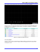
At the completion of the CP1 SigTest Jitter Test the oscilloscope is in the following configuration:
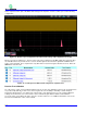
Figure 19 - Oscilloscope Configuration after SigTest CP1 Jitter Test
There are no traces shown on the screen at this time. The parameters displayed are the Tj, Rj and Dj calculated
by SigTest. Additionally, the Maximum Peak-to-peak Jitter, the Average UI, the Bit Rate, and the Minimum
Crossing time are also displayed.
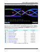
Figure 20 - Test Report from SigTest Jitter Test
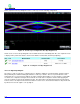
Test 1.3.4 Eye Diagram
The purpose of this test group is to verify that the eye diagram is within the specification limits. For compliance
testing the measurements are made after a compliance channel after applying the reference Continuous Time
Linear Equalizer function.