
Data Sheet


12
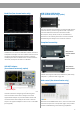
Measurement
Source All channels, All channels in Zoom, Math, All References, History
Number of Measurements Display 5 measurements at the same time
Measurement Range Screen region, Gate region
Measurement Parameters (38 Types)
Vertical (Voltage) Max Highest value in input waveform
Min Lowest value in input waveform
Pk-Pk Difference between maximum and minimum data values
Ampl Difference between top and base in a bimodal signal, or between max and
min in an unimodal signal
Top Value of most probable higher state in a bimodal waveform
Base Value of most probable lower state in a bimodal waveform
Mean Average of all data values
Cmean Average of data values in the rst cycle
Stdev Standard deviation of all data values
Cstd Standard deviation of all data values in the rst cycle
VRMS Root mean square of all data values
Crms Root mean square of all data values in the rst cycle
FOV Overshoot after a falling edge; (base-min)/Amplitude
FPRE Overshoot before a falling edge; (max-top)/Amplitude
ROV Overshoot after a rising edge; (max-top)/Amplitude
RPRE Overshoot before a rising edge; (base-min)/Amplitude
Level@X the voltage value of the trigger point
Horizontal( Time) Period Period for every cycle in waveform at the 50 % level, and positive slope
Freq Frequency for every cycle in waveform at the 50 % level, and positive slope
+Wid Width measured at 50 % level and positive slope
-Wid Width measured at 50 % level and negative slope
Rise Time Duration of rising edge from 10 – 90 %
Fall Time Duration of falling edge from 90 – 10 %
Bwid Time from the rst rising edge to the last falling edge, or the rst falling edge
to the last rising edge at the 50 % crossing
+Dut Ratio of positive width to period
-Dut Ratio of negative width to period
Delay Time from the trigger to the rst transition at the 50 % crossing
Time@Level Time from the trigger to each rising edge at the 50 % crossing.
When Statistics is Off, it shows the time from the trigger to the last rising
edge at the 50 % crossing.
When Statistics is On, it shows the Current, Mean, Min, Max, Standard
Deviation of time from the trigger to each rising edge at the 50 % crossing
in multiple frames (number = Count).
Delay Phase Calculate the phase difference between two edges
FRR Time between the rst rising edges of the two channels
FRF Time from the rst rising edge of channel A to the rst falling edge of channel B
FFR Time from the rst falling edge of channel A to the rst rising edge of channel B
FFF Time from the rst falling edge of channel A to the rst falling edge of channel B
LRR Time from the rst rising edge of channel A to the last rising edge of channel B
LRF Time from the rst rising edge of channel A to the last falling edge of channel B
LFR Time from the rst falling edge of channel A to the last rising edge of channel B
LFF Time from the rst falling edge of channel A to the last falling edge of channel B
Skew Time of source A edge minus time of nearest source B edge
Cursors Manual : Time X1, X2, (X1-X2), (1/ΔT) Voltage Y1, Y2, (Y1-Y2)
Track: Time X1, X2, (X1-X2)
Statistics Current, Mean, Min, Max, Stdev, Count
Counter Hardware 6 bit counter( channels are selectable)
SPECIFICATIONS