Instruction Manual USB2/USB2-HSIC Decode and Trigger
USB2/USB2-HSIC Decode and Trigger Instruction Manual © 2014 Teledyne LeCroy, Inc. All rights reserved. Unauthorized duplication of Teledyne LeCroy documentation materials other than for internal sales and distribution purposes is strictly prohibited. However, clients are encouraged to distribute and duplicate Teledyne LeCroy documentation for their own internal educational purposes. Teledyne LeCroy is a trademark of Teledyne LeCroy, Inc.
Instruction Manual Contents About This Manual Assumptions Compatibility 2 2 2 About the USB2 Options Decode Trigger 3 3 3 USB Decoding Serial Decode Technical Overview Decoding Workflow Setting Up the Decoder Working with the Decode Trace Working with the Result Table Applying Measurements with PROTObus MAG 4 4 5 6 9 12 14 USB Triggering Serial Trigger Technical Overview Linking Decoder to Trigger USB2 Trigger Setup 16 16 16 17 Contact Teledyne LeCroy 21 922295 RevA 1
USB2/USB2-HSIC Decode and Trigger About This Manual Teledyne LeCroy offers an array of toolsets for decoding and debugging serial data streams. These toolsets may be purchased as optional software packages, or are provided standard with SDA and DDA model oscilloscopes. This manual explains how to use the following options. l USB2.
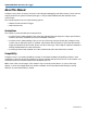
Instruction Manual About the USB2 Options USB 2.0 is a version of the Universal Serial Bus specification, which is used to connect a host controller (typically a PC) to various devices. The 2.0 version brought a higher maximum bandwidth (480 Mb/s) and features such as the Mini-B Connector, Battery Charging, and Micro-USB Cables and Connectors specifications, to name a few.
USB2/USB2-HSIC Decode and Trigger USB Decoding Serial Decode Technical Overview The algorithms described here at a high level are used by all Teledyne LeCroy serial decoders sold for oscilloscopes. They differ slightly for serial data signals that have a clock embedded in data or a clock separate from data. Bit-level Decoding The first software algorithm examines the embedded clock for each message based on a default or userspecified vertical level.
Instruction Manual Decoding Workflow While not required, we recommend the following workflow for decoding: 1. Set up the decoder. 2. Acquire a single burst of relevant data, then run the decoder. NOTE: If the sampling rate (SR) is insufficient to resolve the signal adequately based on the bit rate (BR) setup or clock frequency, the protocol decoding is turned OFF to protect you from incorrect data. The minimum SR:BR ratio required is 4:1.
USB2/USB2-HSIC Decode and Trigger Setting Up the Decoder The main Serial Decode dialog allows you to preset up-to-four, independent decoders, Decode 1 to Decode 4. Each decoder can use different (or the same) protocols and data sources, or have other variations, giving you maximum flexibility to compare different signals or view the same signal from multiple perspectives.
Instruction Manual USB2 Decoder Settings Probe Selection - select One Differential Probe, Two Single Ended Probes or One Single Ended Probe, depending on your physical input setup. If using Two Single Ended Probes, enter your Dp (Data positive) and Dn (Data negative) source channels separately on the Decode Setup dialog to the left. Bus Speed - select Low, Full, or High. HSIC Decoder Settings DataLevel - Enter the crossing level for the data waveform in Volts.
USB2/USB2-HSIC Decode and Trigger Enabling/Disabling the Decoder Once preset, the four decoders can be enabled simultaneously or separately, although this number may be limited depending on the type of source channels selected. Preset decoders can be easily disabled without disrupting the configuration.
Instruction Manual Working with the Decode Trace Reading Waveform Annotations When a decoder is enabled, an annotated waveform appears on the oscilloscope display, allowing you to quickly read the results of the decode. A colored overlay marks significant transitions in the source signal. The overlay contains annotations corresponding to the data itself, any pre/post-message padding, inter-burst periods, etc. Each set of annotations is customized to the protocol or encoding scheme.
USB2/USB2-HSIC Decode and Trigger Zoom of transaction, showing annotation details. HSIC WAVEFORM ANNOTATIONS These overlays appear on an HSIC waveform or its Zoom trace to highlight key elements of the decoded signal (some annotations are not shown on the screen-shot).
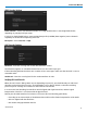
Instruction Manual Searching Waveforms Choosing Search on the Decode Setup dialog opens a Zoom of the original decoded waveform and displays the corresponding Zoom dialog with the standard rescaling controls. Enter the search criteria on the dialog: SearchType - USB element to find. Options include Any, Event, Handshake Packet, Token Packet, Data Packet, Transaction, or Protocol Error. SearchSubtype - Type of the USB element selected in SearchType (e.g.
USB2/USB2-HSIC Decode and Trigger Working with the Result Table By default, a table summarizing the decoder results appears below the grids whenever a decoder is enabled. The result table provides a view of message data as decoded during the most recent acquisition, even when messages are too compact to allow annotation on the waveform trace. The table is displayed only when the View Decode checkbox is marked on the Decode Setup Dialog and a source signal has been decoded using that protocol.
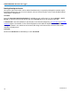
Instruction Manual Customizing the Result Table Follow these steps to change what data appears in the result table: 1. Press the Front Panel Serial Decode button, or choose Analysis > Serial Decode, then open the Decode Setup tab. 2. Touch the Configure Table button. 3. On the View Columns pop-up dialog, check boxes for the columns you want to appear in the table. Clear boxes for any columns you wish to remove. Only those columns selected will appear on the oscilloscope display.
USB2/USB2-HSIC Decode and Trigger Applying Measurements with PROTObus MAG If you have purchased and installed the PROTObus MAG option with your decoder, special measurements designed for debugging serial data streams can be applied to the decoded waveform. These measurements appear in a tabular readout below the grid (the same as for any other measurements) and are in addition to the result table that shows the decoded data. You can set up as many measurements as your oscilloscope has parameter locations.
Instruction Manual l l l MsgToMsg (Message to Message) - Computes the time difference from one protocol message to another protocol message. DeltaMsg (Delta Message) - Computes the time difference between two messages on a single decoded line. Time@Msg (Time at Message) - Time from trigger to each protocol message (meeting specified conditions). l BusLoad - Computes the load of user-defined messages on the bus (as a percent).
USB2/USB2-HSIC Decode and Trigger USB Triggering Serial Trigger Technical Overview TD options provide advanced serial data triggering. Serial data triggering is implemented directly within the hardware of the oscilloscope acquisition system and utilizes the decoder algorithms to recognize userdefined serial data patterns. This allows a recognized pattern to be used to trigger the oscilloscope, while other signals coincident with the desired pattern can be simultaneously captured.
Instruction Manual USB2 Trigger Setup USB2 triggers fall into four basic types of Packet, Protocol Error, Transaction, and Bus Event. The setups for each type of trigger differ significantly and so are described in separate procedures below. Only the first group of settings describing the source Setup is utilized by all the trigger types. To begin, access the Serial Trigger dialog: l Touch the Trigger descriptor box, or choose Trigger > Trigger Setup from the Menu Bar.
USB2/USB2-HSIC Decode and Trigger Transaction Trigger This will trigger upon finding transactions that meet all the Token, Data, and Handshake packet criteria. Options vary depending on the bus speed. The principal difference between a Transaction trigger and a Packet trigger is that for a Transaction trigger, the specified packet types simply need to be found in the transaction, whereas for a Packet trigger, the packet types and values must meet the criteria. 1. Choose Pattern Type Transaction. 2.
Instruction Manual TRIGGER ON TOKEN PATTERN 1. Choose Pattern Type Packet and Category Token. 2. Choose to enter values in Binary or Hexadecimal (Hex) format. The selection propagates throughout the entire trigger setup. Toggling between formats does not result in loss of information, but will transform the appearance of values. 3. Use the three Token # PID controls to define the firt, second, and third token patterns that will fire the trigger. NOTE: Options will vary by bus speed.
USB2/USB2-HSIC Decode and Trigger 4. In Compare Type, choose to compare Data Values or Data Lengths to find a match. 5. If you chose to compare lengths, enter the Cmp. Opr. (operator) and Length (in bytes) that define the trigger criteria (e.g., Trigger if Data0 length is greater than 4 bytes). If you chose to compare values, enter the Cmp. Opr. (operator), At position, and a reference Data (1-16 Bytes) pattern that define the trigger criteria (e.g.
USB2/USB2-HSIC Decode and Trigger Contact Teledyne LeCroy United States and Canada - World Wide Corporate Office Teledyne LeCroy Corporation 700 Chestnut Ridge Road Chestnut Ridge, NY, 10977-6499, USA Ph: 800-553-2769 / 845-425-2000 FAX: 845-578-5985 teledynelecroy.com Support: contact.corp@teledynelecroy.com Sales: customersupport@teledynelecroy.com United States Protocol Solutions Group Teledyne LeCroy Corporation 3385 Scott Boulevard Santa Clara, CA, 95054, USA FAX: 408-727-0800 teledynelecroy.