Instruction Manual Model 1220 Multi - Channel Combustible Monitor DANGER HIGHLY TOXIC AND OR FLAMMABLE LIQUIDS OR GASES MAY BE PRESENT IN THIS MONITORING SYSTEM. PERSONAL PROTECTIVE EQUIPMENT MAY BE REQUIRED WHEN SERVICING THIS SYSTEM. HAZARDOUS VOLTAGES EXIST ON CERTAIN COMPONENTS INTERNALLY WHICH MAY PERSIST FOR A TIME EVEN AFTER THE POWER IS TURNED OFF AND DISCONNECTED. ONLY AUTHORIZED PERSONNEL SHOULD CONDUCT MAINTENANCE AND/OR SERVICING.
Copyright © 1999 Teledyne Analytical Instruments All Rights Reserved. No part of this manual may be reproduced, transmitted, transcribed, stored in a retrieval system, or translated into any other language or computer language in whole or in part, in any form or by any means, whether it be electronic, mechanical, magnetic, optical, manual, or otherwise, without the prior written consent of Teledyne Analytical Instruments, 16830 Chestnut Street, City of Industry, CA 91749-1580.
Specific Model Information The instrument for which this manual was supplied may incorporate one or more options not supplied in the standard instrument. Commonly available options are listed below, with check boxes. Any that are incorporated in the instrument for which this manual is supplied are indicated by a check mark in the box.
IMPORTANT NOTICE The 1220 is a safety monitor. However, it is the responsibility of the user to establish whether or not the total system of instrument, environment, alarm components, and any other relevant devices actually will assure safety in his particular circumstances. Location of the equipment and sensors to insure proper operation is responsibility of the user. The safety checklist outlined here should be treated only as a guide. It is up to the user to establish practical safety precautions.
Table of Contents Introduction 1.1 1.2 Overview........................................................................... Description........................................................................ 1.2.1 System Chassis ............................................................ 1.2.2 Control Unit ................................................................... 1.2.3 Channel Modules .......................................................... 1.2.3.1 Main Featuress of the Channel Module .........
4.2.1 System Power Switch and LED ................................... 4-2 4.2.2 Audible Alarm Switch and Bypass LED ....................... 4-2 4.2.3 Fuses .......................................................................... 4-2 4.2.4 RS485 Port .................................................................. 4-2 4.3 Channel Module Front Panel Controls & Indicators ....... 4-4 4.4 Calibration Procedures .................................................. 4-7 4.4.1 Zero Calibrating a Single Sensor Ch.
Multi-Channel Combustible Monitor Introduction 1 Introduction 1.1 Overview The Teledyne Analytical Instruments (TAI) Model 1220 is a multichannel system that can be used for determining the concentration of combustible gases in an atmosphere at a number of remote locations, and provide alarm information when the combustible gas level exceeds predetermined limits at any one or all of the remote locations.
1 Introduction Model 1220 1.2.1 System Chassis (19” Rack) The System Chassis provides structural support and electrical interconnection for the Control Unit and Channel Modules (up to eight Channel Modules may be installed). These latter plug into the sockets of the system chassis. Terminal strips at the rear of the System Chassis provide for external electrical connections. 1.2.2 Control Unit The Control Unit handles power distribution to the entire system.
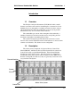
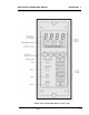
Multi-Channel Combustible Monitor Introduction 1 Model 1220 Combustible Monitor Front Panel Teledyne Analytical Instruments 1-3
1 Introduction • • • • Model 1220 Failure codes and testpoints Two selectable analog outputs (0-10VDC or negative ground 4-20mADC) Extensive, automatic self-test diagnostic testing during operation Compact and versatile design: Small footprint with accessible internal PCBs 1.2.4 Detector The detector is a low temperature, catalytic oxidation, diffusion type sensor. Each detector contains two beads: a catalytically active bead and a thermally identical inert bead.
Multi-Channel Combustible Monitor Operational Theory 2 Operational Theory 2.1 Introduction The Model 1220 combustible gas analyzer is composed of four components: 1. System Chassis 2. Control Unit 3. Channel Modules 4. Combustible Sensors The System Chassis provides structural support and electrical interconnection for a Control Unit and up to eight Channel Modules. Each Channel Module can monitor one or two sensors (dual-sensor option). 2.
2 Operational Theory PRIMARY POWER Model 1220 POWER TO CHANNEL MODULES POWER SWITCH SIGNALS FROM CHANNEL MODULES AUDIBLE ALARM BYPASS DRIVERS RELAYS INTERNAL BUZZER POWER FOR EXTERNAL AUDIBLE ALARMS RELAY CONTACT ACTUATION *HIGH HIGH *CAUTION CAUTION FAILURE FAILURE Control Unit - Block Diagram for operation in the “non fail-safe” mode by setting the configuration jumpers as indicated in the installation section 3.3.2.
Multi-Channel Combustible Monitor 2.4 Operational Theory 2 Channel Module The Model 1220 Combustible Gas Analyzer uses an Intel Microcontroller with on-board RAM and ROM to control all signal processing, input/output, and display functions for the analyzer. The channel power is supplied from two separate universal power supply modules (100-240 VAC), designed to be compatible with most international power sources. The first power supply (triple outputs) supplies the voltages for logic devices.
2 Operational Theory Model 1220 When exposed to a mixture containing gases and oxygen, the measuring bead coating allows the oxygen and combustibles to combine at its surface. The energy produced by this reaction heats the measuring bead. The rise in temperature changes the bead’s resistance and is related to the concentration of the combustible gas. The reaction rate is dependent upon the nature of the particular combustible gas.
Multi-Channel Combustible Monitor Operational Theory 2 The response of a catalytic bead detector to a number of gases is shown in Table 1. For lighter than air gases, the detectors are generally installed above the source; for heavier than air gases, detectors are generally installed below the source. Table 1 Detector Response to Gases COMPOUND LEL* RESPONSE FACTOR Methane 5.0 1.00 Hydrogen 4.0 0.86 Carbon Monoxide 12.5 0.32 Ethane 3.0 1.20 Ethylene 2.7 1.26 Acetylene 2.5 1.
2 Operational Theory Model 1220 M U A to D To CPU Converter X S1 S2 Digital to 0-10 V dc Concentration Analog Converter ± 12 V Test (DAC) 4-20 mA dc Power Supply 2 Concentration AC/DC Analog Output Test + 5, ± 15 V Test s ay el R High Keyboard Caution Central Display & LED Indicators Processing Unit (CPU) Power Supply 1 AC/DC Failure RS-485 Figure 2-3: Block Diagram of the Signal Processing Electronics 2-6 Teledyne Analytical Instruments
Multi-Channel Combustible Monitor Operational Theory 2 2.5.1 Response of Combustible Sensor to Various Gases Response factors have been determined to relate the sensor output of a specific compound to the output obtained using methane. A list of some typical compounds is given in Table 1, along with their LEL (Lower Explosive Limit) values. To determine the output of the sensor to any of the gases listed, compared to the same concentration of methane, multiply the reading obtained by the factor listed.
2 Operational Theory 2-8 Teledyne Analytical Instruments Model 1220
Multi-Channel Combustible Monitor Installation 3 Installation Installation of the analyzer includes: 1. Unpacking the system 2. Mounting the Channel Module and Control Module 3. Making the electrical connections 5. Making the gas connections 6. Testing the installation 3.1 Unpacking the Analyzer Each TAI Model 1220 Combustible Gas Monitoring System is generally shipped with the channel modules and control module installed.
3 Installation Model 1220 3.2 System Chassis The physical dimensions and mounting hole spacing for the System Chassis are given on Drawing D-67849. The System Chassis is designed to fit into a standard 19" rack. It requires 7" panel height and 12.3" depth plus allowance for cabling behind the panel. 3.2.1 Location The System Chassis is designed for installation in a NON HAZARDOUS Environment. 3.2.2 Power The model 1220 is designed to operate from 100/240VAC @ 50/60 Hz.
Multi-Channel Combustible Monitor Installation 3 Care must be observed to ensure that the sensor leads are not inadvertently connected to the signal common (C) or to the power ground while energized. (See Figure 3-1) Note: The maximum loop resistance for cabling to each sensor is 35 W, i.e. the cabling and connections should not exW ceed 35 total, or 35 /W2 = 17.5 onW each side of the sensor (See Figure 3-2). Note that the white wire resistance is not a limiting factor in the Loop Resistance, i.e.
3 Installation Model 1220 Figure 3-2 Maximum Loop Resistance for Sensor Connection The terminals marked "Ext. Audible Alarm" provide an external signal that is activated whenever the audible alarm is activated. By setting jumpers on the Control Unit PCB (see section 3.3), the external signal can be either (1) a contact closure, or (2) a powerline level signal.
Multi-Channel Combustible Monitor Installation 3 3.3 Control Unit In the event that it becomes necessary to remove the Control Unit, primary power to the System Chassis must first be disconnected, and the six small screws around the periphery of the Control Unit front panel removed. The two knurled, slotted jack screws may then be backed out to pull the Control Unit out until it is disengaged from its socket. It may then be slid out of the chassis.
3 Installation Model 1220 Three alarms (CAUTION, HIGH, and FAIL) may be configured for either fail-safe (default) or non-fail-safe operation per the following table: The external audible alarm may be configured to operate in either the fail-safe (default) mode or the non-fail-safe mode. It may also be configured to provide either a contact closure (default) or the incoming line voltage to the external connections.
Multi-Channel Combustible Monitor Installation 3 The internal audible alarm may be disabled by removing JP17. WARNING: It is not recommended to remove JP17 unless there is an external audible alarm in use. With the jumper removed, the audible alarm will not warn personnel about alarm conditions. 3.4 Channel Modules Channel Modules may be removed by first unscrewing the top (retaining) screw and then unscrewing the bottom (jack) screw.
3 Installation Model 1220 module may be accomplished by sliding the module into the chassis until the top and bottom screws can be engaged, engaging them, tightening the bottom (jack) screw to reconnect the module, and then tightening the top (retaining) screw. WARNING: Disconnect power before performing any of the following. These operations should only be performed by a qualified service technician. 3.4.1 Removing the Channel Module Cover In order to perform the actions in the following sections 3.4.
Multi-Channel Combustible Monitor Installation 3 3.4.4 Configuring the Internal Jumper Connections The Channel Module outputs may be configured by setting the internal jumpers. In addition there are several factory preset jumpers configured as shown in the following table. Changing the internal jumpers requires removing the channel module cover as in section 3.4.1. The Channel Module is configured to provide an RS485 communication link with the Control Unit (not available at this time).
3 Installation Model 1220 3.5 Combustible Sensors The sensors should be mounted with their long axis vertical and the sensing surface downward. It is recommended that any terminal lugs be attached to the sensor by soldering as well as by crimping. However, care must be observed to insure that solder does not flow onto the area where the terminal screws must seat, as that can make it difficult to get firm, permanent seating of the screws.
Multi-Channel Combustible Monitor Operation 4 Operation 4.1 Introduction Once the System has been Installed, check all wiring to make certain that it is correct. Check that the POWER switch on the Control Unit is in the “OFF” position, then apply primary power to the system. Continue start-up as follows: 1. Check that AUDIBLE ALARM switch is set to BYPASS mode on the Control Unit. 2. Set the Control Unit POWER switch to ON. The green power lamp and red bypass lamp should be illuminated.
4 Operation Model 1220 4.2 Control Unit Operation 4.2.1 System Power Switch and LED The power to the entire 1220 system is controlled by the System Power Switch. The green System Power LED indicates system power status (ON/ OFF). 4.2.2 Audible Alarm Switch and Bypass LED The Audible Alarm Switch overrides the audible alarm when in the Bypass position. The red Bypass LED lights when the audible alarm is bypassed. 4.2.3 Fuses For fuse replacement/installation, see section 3.3.1 and 3.4.3 4.2.
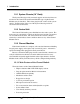
Multi-Channel Combustible Monitor Operation 4 Channel Module Front Panel Controls and Indicators Teledyne Analytical Instruments 4-3
4 Operation Model 1220 4.3 Channel Module Front Panel Controls and Indicators STANDBY Switch - When pressed, this membrane switch places the Channel Module in the standby mode, i.e., removes power from the sensor(s) and extinguishes the LCD display. NOTE: If the relays are configured for fail-safe operation, they will remain energized. If an alarm condition exists, the Channel Module will return to a non-alarm state.
Multi-Channel Combustible Monitor ENTER RUN Operation 4 ENTER Switch - Use this membrane switch in conjunction with the SELECT Switch to select a user-configurable mode and then the option highlighted. RUN Switch - Pressing this membrane switch places the Channel Module in the analysis mode, i.e., the unit is operational. When in one of the four user-configurable modes, all arrows allow you to navigate through the options.
4 Operation Model 1220 NOTE: When one of these modes are selected, the field light flashes indicating which mode the monitor is on. Configuration Display Panel Fields “S1” highlighted indicates that Sensor 1 options may be set. “S2” highlighted indicates that Sensor 2 options may be set. This option is used to zero (“0”) calibrate the Channel Module. This option is used to span calibrate the Channel Module. This option enables a single person to perform both a span and zero calibration.
Multi-Channel Combustible Monitor Operation 4 If “FS” is selected, the associated relay is in the Fail-safe Mode, i.e., the relay is “normally energized”. If “NFS” is selected, the associated relay is in the Non-Fail-safe Mode, i.e., the relay is “normally de-energized”. Sensitivity Gauge The Sensitivity Gauge monitors the life of the sensor. It does so by monitoring successive span procedures throughout the life of the sensor. As the sensor gets older it’s resistance builds, lessening the sensitivity.
4 Operation Model 1220 a. Press the up or down arrow key until the display reads “0”. b. Press ENTER. 4. (B) Disconnect the zero gas from the sensor. 5. (A) If necessary, proceed to the previous or next procedure. Otherwise, press RUN to place the instrument in the analysis mode. 4.4.2 Span Calibrating a Single Sensor Channel Module NOTE: To accomplish the following task, two operators are needed. Operator one at the Control Unit and operator two at the probe.
Multi-Channel Combustible Monitor Operation 4 4.4.3 Zero Calibrating a Dual Sensor Channel Module NOTE: To accomplish the following task, two operators are needed. Operator one at the Control Unit and operator two at the probe. Both operators are involved in the calibration process. They must be in constant communication, by phone or other means. (A) = Operator One at the Control Unit (B) = Operator Two at the probe 1. (A) At the Front Panel of the Channel Module to be calibrated: a. Press SELECT. b.
4 Operation Model 1220 4.4.5 Using the “1MAN” Calibration Option The two following calibration procedure can be performed by one technician. 4.4.5.1 Zero and Span Calibrating a Single Sensor Channel Module 1. At the Front Panel of the Channel Module to be calibrated: a. Press SELECT. b. Use the right or left arrow key to highlight the 1MAN option. c. Press ENTER. 2. At the remote probe site, introduce certified span gas to the sensor. 3. Wait 60 seconds so that the reading can stabilize. 4.
Multi-Channel Combustible Monitor Operation 4 2. To calibrate the second sensor, perform this procedure again beginning with Step “1b”. 4.5 Alarm Configuration Procedures 4.5.1 Defining the Setpoint for the High or Caution Alarm NOTE: (Applies to Dual Sensor Instruments Only) The High and Caution Alarm relays are shared by both sensors, i.e., only one setpoint for the High Alarm and one setpoint for the Caution Alarm can be defined. 1. At the Front Panel of the Channel Module to be configured: a.
4 Operation Model 1220 4.5.2.2 Setting the Latching or Non-Latching Mode 1. At the Front Panel of the Channel Module to be configured: a. Press SELECT twice to enter the “Alarm Configuration” Mode. (“H” {High} will be flashing.) b. Use the up or down arrow key to highlight the appropriate alarm to be defined (“H” = High Alarm or “C” = Caution Alarm). c. Use the left or right arrow key to highlight the “LCH” option. d. Press ENTER. e.
Multi-Channel Combustible Monitor Operation 4 2. If necessary, proceed to the previous or next procedure. Otherwise, press RUN to place the instrument in the analysis mode. Passcode: Press the Down arrow key followed by the Right arrow key. 4.8 Setting the Sensitivity Gauge NOTE: The sensitivity gauge can only be adjusted when performing a local (Paragraph 4.3) or “1MAN” (Paragraph 4.4.5.1) span calibration. Recommendations: 1.
4 Operation Model 1220 4.10 FAIL Alarm Conditions The possible FAIL Alarm Conditions are: - A sensor fails. - One of the power suppliers fails. - 0-10V Output fails. - The ADC times out without a proper end-of-conversion (EOC). Whenever a failure is detected, the FAIL alarm is activated: the blue LED turns on, the alarm relay is de-energized (the FAIL relay is FAILSAFE, and the audible alarm is activated. The power supplies to both sensors are disabled.
Multi-Channel Combustible Monitor Operation 4 amounts (percentages) of methane mixed with air. Table II lists calibration factors for the TAI Combustible gas sensor which can be used to calibrate these detectors to indicate the percent LEL of the specific gases. These calibration factors are based on the use of methane in the air as the calibration gas and take into account both relative response and LEL of the specific gases.
4 Operation Model 1220 TABLE II Calibration Factors for TAI Combustible Gas Sensor COMPOUND CALIBRATION FACTOR Methane 20 Hydrogen 29 Carbon Monoxide 25 Ethane 28 Ethylene 29 Acetylene 29 Propane 32 Propylene 38 Butane 34 Cyclohexane 53 Heptane 60 Pentane 46 Toluene 56 Ethylene Oxide 37 Methyl Ethyl Ketone 58 Methyl Acrylate 61 Hexane 61 4-16 Teledyne Analytical Instruments
Multi-Channel Combustible Monitor Failure and Error Codes 5 Failure and Error Codes 5.
5 Failure and Error Codes 5.
Multi-Channel Combustible Monitor Appendix Appendix A-1 Specification Range: 0-100% LEL Combustible Gas in Air (Methane equivalent) Number of Channels: Up to eight channels Repeatability: 2 % of full scale Accuracy: ±2% of full scale at constant tempera- ture Response Time: 90% in less than 15 seconds Operating Temperature: 0 to 50oC Temperature Stability: ±1% over 10oF Alarms: Two Adjustable Alarm Point plus Failure Alarm Indicators illuminate at Alarm Setpoint.
Appendix Model 1220 Power Requirements: System Enclosure: Relay 100-240 VAC 50/60 Hz Control Module fits standard 19” Rack Dimensions: 7” H x 12.3” D x 19” W Maximum Loop Resistance for Sensor Connections/Cabling: 35 W Maximum Loop Resistance for 4-20 mA OUTPUT: 600 W Sensor Probe Mounting: 2 MTG. Holes , 3/16” Diameter, 2 3/ 8” C-TO-C (custom probes for special applications). Field Connections: Barrier-Type Terminal Strips with screw connections.
Multi-Channel Combustible Monitor Appendix Orders should be sent to: TELEDYNE Analytical Instruments 16830 Chestnut Street City of Industry, CA 91749-1580 Phone (626) 934-1500, Fax (626) 961-2538 TWX (910) 584-1887 TDYANYL COID Web: www.teledyne-ai.com or your local representative.
Appendix A-4 Model 1220 Teledyne Analytical Instruments