Thermal Conductivity Analyzer OPERATING INSTRUCTIONS FOR Model 2010B Thermal Conductivity Analyzer Teledyne A nalytical In strum ents 0.0 AL-1 % Anlz 2010B Therm al C onductivity A nalyzer DANGER HIGHLY TOXIC AND OR FLAMMABLE LIQUIDS OR GASES MAY BE PRESENT IN THIS MONITORING SYSTEM. PERSONAL PROTECTIVE EQUIPMENT MAY BE REQUIRED WHEN SERVICING THIS SYSTEM. HAZARDOUS VOLTAGES EXIST ON CERTAIN COMPONENTS INTERNALLY WHICH MAY PERSIST FOR A TIME EVEN AFTER THE POWER IS TURNED OFF AND DISCONNECTED.
Model 2010B Copyright © 1998 Teledyne Analytical Instruments All Rights Reserved. No part of this manual may be reproduced, transmitted, transcribed, stored in a retrieval system, or translated into any other language or computer language in whole or in part, in any form or by any means, whether it be electronic, mechanical, magnetic, optical, manual, or otherwise, without the prior written consent of Teledyne Analytical Instruments, 16830 Chestnut Street, City of Industry, CA 917491580.
Thermal Conductivity Analyzer Table of Contents Specific Model Information ................................. iv Part I: Control Unit, Model 2010B ......... Part I: 1-1 Part II: Analysis Unit, Model 2010B ...... Part II: 1-1 Appendix .........................................................
Model 2010B Specific Model Information The instrument for which this manual was supplied may incorporate one or more options not supplied in the standard instrument. Commonly available options are listed below, with check boxes. Any that are incorporated in the instrument for which this manual is supplied are indicated by a check mark in the box.
Thermal Conductivity Analyzer Table of Contents 1 Introduction 1.1 1.2 1.3 1.4 1.5 1.6 1.7 1.8 Overview ........................................................................ Typical Applications ....................................................... Main Features of the Analyzer ....................................... Model Designations ....................................................... Operator Interface (Front Panel) ....................................
Model 2010B 4.3 The System Function ..................................................... 4-4 4.3.1 Setting the Display ................................................. 4-5 4.3.2 Setting up an Auto-Cal ........................................... 4-5 4.3.3 Password Protection .............................................. 4-6 4.3.3.1 Entering the Password ................................... 4-7 4.3.3.2 Installing or Changing the Password ............. 4-7 4.3.4 Logging Out .................................
Thermal Conductivity Analyzer 5.5 Major Internal Components ........................................... 5-3 5.6 Cleaning ......................................................................... 5-5 5.7 Phone Numbers ............................................................. 5-5 Appendix A-1 Specifications ................................................................. A-1 A-2 Recommended 2-Year Spare Parts List ......................... A-3 A-3 Drawing List ...........................................
Model 2010B DANGER COMBUSTIBLE GAS USAGE WARNING The customer should ensure that the principles of operating of this equipment are well understood by the user. Misuse of this product in any manner, tampering with its components, or unauthorized substitution of any component may adversely affect the safety of this instrument.
Thermal Conductivity Analyzer Part I: Control Unit Introduction 1.1 Overview The Model 2010 is a family of split configuration conductivity analyzers. Each analyzer consist of a Control Unit suitable for installation in a general purpose area-enclosure rated NEMA-4, and a Analysis Unit which is housed in an explosion-proof enclosure. The Analysis Unit enclosure is rated for NEMA 4/7 Class I, Div. 1, Groups B,C,D and is approved by U/L and CSA.
Model 2010B 1 Introduction 1.2 Typical Applications A few typical applications of the Model 2010B are: • Power generation • Air liquefaction • Chemical reaction monitoring • Steel manufacturing and heat treating • Petrochemical process control • Quality assurance • Refrigeration and storage • Gas proportioning control. 1.
Thermal Conductivity Analyzer Part I: Control Unit • Wide range of custom applications, ranges, and linearization. • Microprocessor based electronics: 8-bit CMOS microprocessor with 32 kB RAM and 128 kB ROM. • Auto and remote calibration capabilities. • Four analog outputs: two for measurement (0–1 V dc and Isolated 4–20 mA dc) and two for range identification. • Compact and versatile design: Small footprint, yet internal components are accessible. 1.
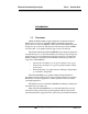
Model 2010B 1 Introduction O u te r D o or (O pe n) Teledyne An alytical Instrum ents V iew in g W in dow 0.0 AL-1 % Anlz D ig ital M ete r LC D S creen In ne r D o or Latch (P ressing the latch button w ill open the inn er D oor) O u te r D o or Latch C ontrol Pan el 2010B T he rm al C o ndu ctivity A na lyzer Figure 1-1: Model 2010B Front Panel • Span Span calibrate the analyzer. • Zero Zero calibrate the analyzer. • Alarms Set the alarm setpoints and attributes.
Thermal Conductivity Analyzer Part I: Control Unit Digital Meter Display: The meter display is a VFD device that produces large, bright, 7-segment numbers that are legible in any lighting. It produces a continuous trace readout from 0-9999 ppm or a continuous percent readout from 1-100 %. It is accurate across all analysis ranges. Alphanumeric Interface Screen: The VDF screen is an easy-to-use interface between operator and analyzer.
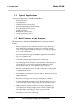
Model 2010B 1 Introduction Figure 1-2: Model 2010B Rear Panel • Power Connection 85-250 V AC power source. • Analog Outputs 0-1 V dc concentration plus 0-1 V dc range ID, and isolated 4-20 mA dc plus 4-20 mA dc range ID.
Thermal Conductivity Analyzer Part I: Control Unit • Alarm Connections 2 concentration alarms and 1 system alarm. • RS-232 Port Serial digital concentration signal output and control input. • Remote Probe Used in the 2010B to interface the external Analysis Unit. • Remote Span/Zero Digital inputs allow external control of analyzer calibration. • Calibration Contact To notify external equipment that instrument is being calibrated and readings are not monitoring sample.
Model 2010B 1 Introduction 1-8 Part I Teledyne Analytical Instruments
Thermal Conductivity Analyzer Part I: Control Unit Operational Theory 2.1 Introduction The analyzer is composed of two subsystems: 1. Thermal Conductivity Sensor 2. Electronic Signal Processing, Display and Control. The sensor is a thermal conductivity comparator that continuously compares the thermal conductivity of the sample gas with that of a reference gas having a known conductivity.
2 Operational Theory Model 2010B Figure 2-1: Thermal Conductivity Cell Operating Principle If the thermal conductivities of the gases in the two chambers are different, the Wheatstone bridge circuit unbalances, causing a current to flow in its detector circuit. The amount of this current can be an indication of the amount of impurity in the sample gas, or even an indication of the type of gas, depending on the known properties of the reference and sample gases.
Thermal Conductivity Analyzer Part I: Control Unit 2.2.3 Effects of Flowrate and Gas Density Because the flowrate of the gases in the chambers affects their cooling of the heated filaments, the flowrate in the chambers must be kept as equal, constant, and low as possible. When setting the sample and reference flowrate, note that gases lighter than air will have an actual flowrate higher than indicated on the flowmeter, while gases heavier than air will have an actual flowrate lower than indicated.
2 Operational Theory Model 2010B removing the back panel. Figure 2-2 is a block diagram of the Analyzer electronics.
Thermal Conductivity Analyzer Part I: Control Unit In the presence of dissimilar gases the sensor generates a differential voltage across its output terminals. A differential amplifier converts this signal to a unipolar signal, which is amplified in the second stage, variable gain amplifier, which provides automatic range switching under control of the CPU. The output from the variable gain amplifier is sent to an 18 bit analog to digital converter.
2 Operational Theory 2-6 Part I Teledyne Analytical Instruments Model 2010B
Thermal Conductivity Analyzer Part I: Control Unit Installation Installation of the Model 2010B Analyzer includes: 1. Unpacking 2. Mounting 3. Gas connections 4. Electrical connections 5. Testing the system. 3.1 Unpacking the Analyzer The analyzer is shipped ready to install and prepared for operation. Carefully unpack the analyzer and inspect it for damage. Immediately report any damage to the shipping agent. 3.
3 Installation Model 2010B N P T Fittings supplied by custo m e r V iew ing W indow 0.0 AL-1 % Anlz O u ter D oor Latch HHinge Figure 3-1: Front Panel of the Model 2010B Control Unit .
Thermal Conductivity Analyzer 3.3 Part I: Control Unit Electrical Connections (Rear Panel) Figure 3-3 shows the Model 2010B Electrical Connector Panel. There are terminal blocks for connecting power, communications, and both digital and analog concentration outputs. For safe connections, ensure that no uninsulated wire extends outside of the connectors they are attached to. Stripped wire ends must insert completely into terminal blocks.
3 Installation Model 2010B DANGER: POWER IS APPLIED TO THE INSTRUMENT'S CIRCUITRY AS LONG AS THE INSTRUMENT IS CONNECTED TO THE POWER SOURCE. THE RED I/O SWITCH ON THE FRONT PANEL IS FOR SWITCHING POWER ON OR OFF TO THE DISPLAYS AND OUTPUTS ONLY. NOTE: AC POWER MAY BE PRESENT ON THE RELAY CONTACTS WHEN THE POWER CORD IS REMOVED! The Control Unit is universal power 100-240V, 50-60 Hz. The Analysis Unit requires 110 or 220 VAC and is selectable via switch located inside the explosion-proof enclosure. 3.3.
Thermal Conductivity Analyzer Part I: Control Unit Figure 3-4: Analog Output Connections Examples: The analog output signal has a voltage which depends on gas concentration relative to the full scale of the range. To relate the signal output to the actual concentration, it is necessary to know what range the instrument is currently on, especially when the analyzer is in the autoranging mode. The signal output for concentration is linear over the currently selected analysis range.
3 Installation Model 2010B To provide an indication of the range, the Range ID analog output terminals are used. They generate a steady preset voltage (or current when using the current outputs) to represent a particular range. Table 3-2 gives the range ID output for each analysis range. Table 3-2: Analog Range ID Output—Example Range Range 1 Voltage (V) 0.25 Current (mA) Application 8 0-1 % H2 in N2 Range 2 0.50 12 0-10 % H2 in N2 Range 3 0.75 16 0-1 % H2 in Air Range 4 (Cal) 1.
Thermal Conductivity Analyzer Part I: Control Unit Actuates when self test fails. (Reset by pressing I/O button to remove power. Then press I/O again and any other button EXCEPT System to resume. Further detail can be found in chapter 4, section 4-5. Figure 3-5: Types of Relay Contacts 3.3.5 Digital Remote Cal Inputs Accept 0 V (off) or 24 V dc (on) inputs for remote control of calibration. (See Remote Calibration Protocol below.) Zero: Floating input.
3 Installation Model 2010B When the contact is OPEN, the analyzer is analyzing, the Remote Cal Inputs are being polled, and a zero or span command can be sent. When the contact is CLOSED, the analyzer is already calibrating. It will ignore your request to calibrate, and it will not remember that request. Once a zero or span command is sent, and acknowledged (contact closes), release it.
Thermal Conductivity Analyzer Part I: Control Unit 3.3.8 RS-232 Port The digital signal output is a standard RS-232 serial communications port used to connect the analyzer to a computer, terminal, or other digital device. It requires a standard 9-pin D connector. Output: The data output is status information, in digital form, updated every two seconds.
3 Installation Model 2010B Table 3-4: Required RS-232 Options Parameter Baud Byte Parity Stop Bits Message Interval Setting 2400 8 bits none 1 2 seconds 3.3.9 Remote Probe Connector The 2010B is a single-split configuration analyzer, the Remote Probe connector is used to interface the Analysis Unit. See Figure 3-6. S PA N IN S A M P L E IN ZE RO IN E X H AU S T +15V Tu rn cw to ho ld ccw to lo ose n w ire. S w itch in g G rou n d In se rt w ire h ere.
Thermal Conductivity Analyzer Part I: Control Unit Figure 3-7: FET Series Resistance 3.4 Testing the System Before plugging the instrument into the power source: • Check the integrity and accuracy of the gas connections. Make sure there are no leaks. • Check the integrity and accuracy of the electrical connections. Make sure there are no exposed conductors • Check that the pressure and flow of all gases are within the recommended levels, and appropriate for your application.
3 Installation 3-12 Part I Model 2010B Teledyne Analytical Instruments
Thermal Conductivity Analyzer Part I: Control Unit Operation 4.1 Introduction Although the Model 2010B is usually programmed to your application at the factory, it can be further configured at the operator level, or even, cautiously, reprogrammed. Depending on the specifics of the application, this might include all or a subset of the following procedures: • Setting system parameters: • Establish a security password, if desired, requiring Operator to log in.
4 Operation Model 2010B The Enter button is used to accept any new entries on the VFD screen. The Escape button is used to abort any new entries on the VFD screen that are not yet accepted by use of the Enter button. Figure 4-1 shows the hierarchy of functions available to the operator via the function buttons. The six function buttons on the analyzer are: • Analyze. This is the normal operating mode.
Thermal Conductivity Analyzer Part I: Control Unit System CONTRAST Set LCD Contrast AUTO-CAL Span/Zero Off/On Span/Zero Timing PASSWORD Enter Password Change Yes/No LOGOUT Secure Sys & Analyze Only Contrast Function is DISABLED (Refer to Section 1.
4 Operation Model 2010B 4.3 The System Function The subfunctions of the System function are described below. Specific procedures for their use follow the descriptions: • • • • • • • • 4-4 Part I AUTO-CAL: Used to define an automatic calibration sequence and/or start an AUTO-CAL. PWD: Security can be established by choosing a 3 digit password (PWD) from the standard ASCII character set.
Thermal Conductivity Analyzer Part I: Control Unit 4.3.1 Setting the Display Contrast Function is DISABLED (Refer to Section 1.6) If you cannot read anything on the VFD after first powering up: 1. Observe LED readout. a. If LED meter reads 8.8.8.8.8., go to step 3. b. If LED meter displays anything else, go to step 2. 2. Press I/O button twice to turn Analyzer OFF and ON again. LED meter should now read 8.8.8.8.8.. Go to step 3. 4.3.
4 Operation Model 2010B Use < > arrows to blink AUTOCAL, and press Enter. A new screen for ZERO/SPAN set appears. ZERO in Ød Øh off SPAN in Ød Øh off Press < > arrows to blink ZERO (or SPAN), then press Enter again. (You won’t be able to set OFF to ON if a zero interval is entered.) A Span Every ... (or Zero Every ...) screen appears. Zero schedule: OFF Day: Ød Hour: Øh Use ∆ ∇ arrows to set an interval value, then use < > arrows to move to the start-time value.
Thermal Conductivity Analyzer 4.3.3.1 Part I: Control Unit Entering the Password To install a new password or change a previously installed password, you must key in and ENTER the old password first. If the default password is in effect, pressing the ENTER button will enter the default TAI password for you. Press System to enter the System mode. Contrast Function is DISABLED (Refer to Section 1.
4 Operation Model 2010B If you chose Enter to change the password, the password assignment screen appears. Select new password TAI Enter the password using the < > arrow keys to move back and forth between the existing password letters, and the ∆ ∇ arrow keys to change the letters to the new password. The full set of 94 characters available for password use are shown in the table below.
Thermal Conductivity Analyzer Part I: Control Unit NOTE:If you log off the system using the LOGOUT function in the system menu, you will now be required to re-enter the password to gain access to Alarm, and Range functions. 4.3.4 Logging Out The LOGOUT function provides a convenient means of leaving the analyzer in a password protected mode without having to shut the instrument off.
4 Operation Model 2010B RUNNING DIAGNOSTIC Testing Preamp Cell When the testing is complete, the results are displayed. Power: OK Analog: OK Cell: 2 Preamp: 3 The module is functioning properly if it is followed by OK. A number indicates a problem in a specific area of the instrument. Refer to Chapter 5 Maintenance and Troubleshooting for number-code information. The results screen alternates for a time with: Press Any Key To Continue... Then the analyzer returns to the initial System screen. 4.3.
Thermal Conductivity Analyzer Part I: Control Unit The leftmost digit (under Dpt) is the number of the data point being monitored. Use the ∆∇ keys to select the successive points. The INPUT value is the input to the linearizer. It is the simulated output of the analyzer. You do not need to actually flow gas. The OUTPUT value is the output of the linearizer. It should be the ACTUAL concentration of the span gas being simulated. If the OUTPUT value shown is not correct, the linearization must be corrected.
4 Operation Model 2010B The analyzer is calibrated using reference, zero, and span gases. Gas requirements are covered in detail in chapter 3, section 3.4 Gas Connections. Check that calibration gases are connected to the analyzer according to the instructions in section 3.4, observing all the prescribed precautions. Note: Shut off the gas pressure before connecting it to the analyzer, and be sure to limit pressure to 40 psig or less when turning it back on.
Thermal Conductivity Analyzer Part I: Control Unit The beginning zero level is shown in the upper left corner of the display. As the zero reading settles, the screen displays and updates information on Slope= in percent/second (unless the Slope starts within the acceptable zero range and does not need to settle further). The system first does a course zero, shown in the lower right corner of the screen as CZero, for 3 min, and then does a fine zero, and displays FZero, for 3 min.
4 Operation Model 2010B ####.## % H2 Slope=#.### SZero N2 Generally, you have a good zero when Slope is less than 0.05 ppm/s for about 30 seconds. Once zero settling completes, the information is stored in the analyzer’s memory, and the instrument automatically returns to the Analyze mode. 4.4.1.3 Cell Failure Cell failure in the 2010B is usually associated with inability to zero the instrument with a reasonable voltage differential across the Wheatstone bridge.
Thermal Conductivity Analyzer 4.4.2.1 Part I: Control Unit Auto Mode Spanning Observe all precautions in sections 4.4 and 4.4.2, above. Press Span to enter the span function. The screen that appears allows you to select whether the span calibration is to be performed automatically or manually. Use the ∆∇ arrow keys to toggle between AUTO and MAN span settling. Stop when AUTO appears, blinking, on the display. Select span mode: AUTO Press Enter to move to the next screen. Span Val: 2Ø.
4 Operation Model 2010B units, as necessary. When you have set the concentration of the span gas you are using, press Enter to begin the Span calibration. Press Enter to enter the span value into the system and begin the span calibration. Once the span has begun, the microprocessor samples the output at a predetermined rate. It calculates the difference between successive samplings and displays this difference as Slope on the screen. It takes several seconds for the first Slope value to display.
Thermal Conductivity Analyzer Part I: Control Unit • Both high (high and high-high) alarms, or • One high and one low alarm, or • Both low (low and low-low) alarms. 2. Are either or both of the alarms to be configured as failsafe? In failsafe mode, the alarm relay de-energizes in an alarm condition. For non-failsafe operation, the relay is energized in an alarm condition. You can set either or both of the concentration alarms to operate in failsafe or non-failsafe mode. 3.
4 Operation Model 2010B Use the ∆ ∇ keys to choose between % or ppm units. Then press Enter to move to the next screen. AL1: 1ØØØ ppm HI Dft:N Fs:N Ltch:N Five parameters can be changed on this screen: • Value of the alarm setpoint, AL1: #### • Out-of-range direction, HI or LO • Defeated? Dft:Y/N (Yes/No) • Failsafe? Fs:Y/N (Yes/No) • Latching? Ltch:Y/N (Yes/No). • To define the setpoint, use the < > arrow keys to move the blinking over to AL1: ####. Then use the ∆∇ arrow keys to change the number.
Thermal Conductivity Analyzer Part I: Control Unit In the AUTO screen, you are further allowed to select which gas application (PREVIOUSLY defined in System function) to run. 4.6.1 Manual (Select/Define Range) Screen The Manual range-switching mode allows you to select a single, fixed analysis range. It then allows you to redefine the upper and lower limits, for the range. Press Range key to start the Range function.
4 Operation Model 2010B the next lower range, the instrument switches to the lower range. A corresponding shift in the DC concentration output, and in the range ID outputs, will be noticed. The autoranging feature can be overridden so that analog output stays on a fixed range regardless of the contaminant concentration detected. If the concentration exceeds the upper limit of the range, the DC output will saturate at 1 V dc (20 mA at the current output).
Thermal Conductivity Analyzer Part I: Control Unit 4.6.3 Precautions The Model 2010B allows a great deal of flexibility in choosing ranges for automatic range switching. However, there are some pitfalls that are to be avoided.
4 Operation Model 2010B Escape button in many cases also switches the analyzer back to the Analyze function. Alternatively, you can press the Analyze button at any time to return to analyzing your sample. The Analyze function screen shows the impurity concentration and the application gases in the first line, and the range in the second line. In the lower right corner, the abbreviation Anlz indicates that the analyzer is in the Analyze mode.
Thermal Conductivity Analyzer Part I: Control Unit MODEL APPLICATION SELF_TEST ALGORITHM Now you will be able to select the APPLICATION and ALGORITHM set-up functions. 4.8.1 The Set Range Screen The Set Range screen allows reprogramming of the three analysis ranges and the calibration range (including impurity gas, background gas, low end of range, high end of range, and % or ppm units). Original programming is usually done at the factory according to the customer’s application.
4 Operation Model 2010B MODEL APPLICATION SELF_TEST ALGORITHM Use the < > arrow keys again to move the blinking to APPLICATION and press Enter. Sel rng to set appl: > Ø1 Ø2 Ø3 CAL < Use the ∆∇ arrow keys to increment/decrement the range number to 01, 02, 03, or CAL, and press Enter. Imp: H2 Bck: N2 FR:Ø TO:1Ø % Use the < > arrow keys to move to Imp: (impurity), Bck: (background), FR: (from—lower end of range), TO: (to—upper end of range), and PPM or %.
Thermal Conductivity Analyzer Part I: Control Unit 4.8.2 The Curve Algorithm Screen The Curve Algorithm is a linearization method. It provides from 1 to 9 intermediate points between the ZERO and SPAN values, which can be normalized during calibration, to ensure a straight-line input/output transfer function through the analyzer. Each range is linearized individually, as necessary, since each range will usually have a totally different linearization requirement.
4 Operation Model 2010B If the OUTPUT value shown is not correct, the linearization must be corrected. Press ESCAPE to return to the previous screen. Select and Enter SET UP to Calibration Mode screen. Select algorithm mode : AUTO There are two ways to linearize: AUTO and MANUAL: The auto mode requires as many calibration gases as there will be correction points along the curve. The user decides on the number of points, based on the precision required.
Thermal Conductivity Analyzer Part I: Control Unit After each point is entered, the data-point number increments to the next point. Moving from the lowest to the highest concentration, use the ∆∇ keys to set the proper values at each point. Dpt INPUT OUTPUT 0 Ø.ØØ Ø.ØØ Repeat the above procedure for each of the data points you are setting (up to nine points: 0-8). Set the points in unit increments. Do not skip numbers. The linearizer will automatically adjust for the number of points entered.
4 Operation Model 2010B 5. Use the ∆∇ keys to set the proper value of calibration gas, and Enter. Repeat this step for each cal-point number as it appears in the Input (x) parentheses. 6. Repeat step 5 for each of the special calibration gases, from the lowest to the highest concentrations. Press Escape when done. To end the session: If started with the RS-232, send: st st to the analyzer from the computer. If started through the front panel, turn the instrument off and back on.
Thermal Conductivity Analyzer Part I: Control Unit 2. Use LEFT/RIGHT key to move to the range that is specified as inverting output. 3. Press and hold DOWN key for approximately 5 to 7 seconds. 4. Press ENTER key. NOTE: If the inverting has been setup, “i” shall display on the left bottom corner. Otherwise, the left bottom corner display ”n”. If more that one range is specified an inverting output, repeat steps 1 to 4. 4.9.
4 Operation Model 2010B 6. Press and hold the RIGHT key for approximate 5 to 7 seconds. 7. Select AUTO and set the reading to span gas level. Press ENTER key. Repeat steps 1 to 7 if more than two ranges need to be setup.
Thermal Conductivity Analyzer Part I: Control Unit Maintenance 5.1 Routine Maintenance Aside from normal cleaning and checking for leaks at the gas connections, routine maintenance is limited to replacing fuses, and recalibration. For recalibration, see Section 4.4 Calibration. WARNING: SEE WARNINGS ON THE TITLE PAGE OF THIS MANUAL. 5.2 System Self Diagnostic Test 1. Press the System button to enter the system mode. 2. Use the < > arrow keys to move to More, and press Enter. 3.
5 Maintenance Model 2010B Preamp 0 OK - > 0 means one or more gain have a high offset, e.g. 204 means highest gain has an offset. This error is common on sealed air cells. Cell 5.3 NOTE: 0 OK 1 Failed (open filament, short to ground, no power.) 2 Unbalance (deterioration of filaments, blocked tube) VFD Display When a vacuum Fluorescent Display is used, It will not require contrast adjustment.
Thermal Conductivity Analyzer Part I: Control Unit Figure 5-1: Removing Fuse Cap and Fuse from Holder 3. Replace fuse by reversing process in step 1. Remove Power to the instrument before changing fuses. 5.5 Major Internal Components The Interconnection Panel and the Front Panel PCBs are accessed by unlatching and swinging open the front door, as described earlier. WARNING: SEE WARNINGS ON THE TITLE PAGE OF THIS MANUAL.
5 Maintenance 5.6 Model 2010B Cleaning If instrument is unmounted at time of cleaning, disconnect the instrument from the power source. Close and latch the front-panel access door. Clean outside surfaces with a soft cloth dampened slightly with plain clean water. Do not use any harsh solvents such as paint thinner or benzene. For mounted instruments, DO NOT wipe the front panel while the instrument is controlling your process. Clean the front panel as prescribed in the above paragraph. 5.
Part II: Analysis Unit OPERATING INSTRUCTIONS Model 2010B Thermal Conductivity Analyzer Part II: Analysis Unit NEC Type Part Number D-70089 Teledyne Analytical Instruments Part II: i
Model 2010B Thermal Conductivity Anal yz er Analyz yzer Table of Contents 1 Introduction 1.1 Overview ........................................................................ 1-1 1.2 Connections ................................................................... 1-1 1.3 Electrical Connector Panel ............................................ 1-2 2 Installation 2.1 2.2 2.3 2.4 2.5 2.6 2.7 2.8 2.9 2.10 2.11 2.12 Unpacking the Analysis Unit ..........................................
Thermal Conductivity Analyzer Part II: Analysis Unit Introduction 1.1 Overview The Analytical Instruments Model 2010B Analysis Unit is a versatile remotely controlled instrument for measuring a component gas in a background gas, or in a specific mixture of background gases. Part 1 of this manual covers the Control Unit. Part II, this part, covers the Model 2010B NEC type explosion proof Analysis Unit only. 1.
1 Introduction Model 2010B Figure 1-1: Outline Diagram of 2010B Analysis Unit • REFERENCE IN This is the gas input from the flowing reference gas source. This gas connector should have a flowmeter with a range of 20-100 cc/ min. • SPAN/ZERO These gas inputs have the same requirements as the sample in connection. • VENTS Sample and reference gas vents must be returned to areas of equal pressure. The actual tubing size and connection type will depend on actual options selected.
Thermal Conductivity Analyzer Part II: Analysis Unit Figure 1-2: Electrical Connector/Control Panel • Power In Power input terminals for electric heater. Requires 110 or 220 V ac, depending on position of the Voltage Selector switch. Use 50/60 Hz. CAUTION: Check the position of the Voltage Selector switch BEFORE applying power to the Power Input terminals. • Voltage Selector Power input selector switch for electric heater.
1 Introduction 1-4: Part II Model 2010B Teledyne Analytical Instruments
Thermal Conductivity Analyzer Part II: Analysis Unit Installation Installation of the Model 2010B Analyzer includes: 1. Unpacking, mounting, and interconnecting the Control Unit and the Analysis Unit 2. Making gas connections to the system 3. Making electrical connections to the system 4. Testing the system. 2.1 Unpacking the Analysis Unit The analyzer is shipped with all materials needed to install and prepare the system for operation. Carefully unpack the Analysis Unit and inspect it for damage.
2 Installation Model 2010B Figure 3-1: 2010 Analysis Unit with Auto-Cal & Gas Panel options 2-3 Sample System Design Gas Connector and Selector Panels for specific applications are available at additional cost . These panels are designed to substitute a standard front panel. For those customers wishing to incorporate their own sample system, electronic input/output ports are provided on the rear panel for the operation of solenoid valves under the complete control of the Model 2010B electronics.
Thermal Conductivity Analyzer Part II: Analysis Unit NOTE: The sample-line pressure regulator should be installed as close to the sample point as possible to minimize sampleline lag time. NOTE: An additional option is available for SEALED reference application. This option would not have the reference Gas Flow Meter, Piping and Fittings. 2-4 Pressure and Flowrate Regulation Appropriate pressure reducing regulators must be installed at all gas supply sources.
2 Installation Model 2010B ambient pressures, and pressures must vary no more than the normal barometric changes. 2-6 SAMPLE Gas In the standard model, sample and calibration gases are introduced through the SAMPLE fitting. The gases must be Tee'd into the Sample inlet with appropriate valves. The gas pressure in should be well regulated. The sample line pressure regulator should be installed as close to the sample line as possible to minimize sample line lag time.
Thermal Conductivity Analyzer 2-8 Part II: Analysis Unit ZERO Gas For the ZERO gas, a supply of the background gas, usually containing none of the impurity, is required to zero the analyzer during calibration. For suppressed zero ranges the zero gas must contain the low-end concentration of the impurity. NOTE:Because most cylinder gases are between 99.95 and 99.98% pure, it is highly recommended that the same cylinder of gas be used for both REFERENCE and ZERO gas.
2 Installation Model 2010B Figure 3-4: Control Unit (CU) to Analysis Unit (AU) Connector If you use your own gas control valves, use the interconnect diagram in Figure 3-4 for the valves. The sensor and thermistor remain connected as in Figure 3-5, above. (See drawing D-73170 for wire recommendations.) Figure 3-5: Remote Probe Connector Pinouts The voltage from the solenoid outputs is nominally 0 V for the OFF and 15 V dc for the ON conditions.
Thermal Conductivity Analyzer Part II: Analysis Unit Figure 3-6: FET Series Resistance 2-11 Signal Wiring Recommendations The signal leads are the bias and sensor leads ref fig. 3.4, and reference D-73170 interconnection diagram. The maximum interconnection distances between the 2010 control unit and the analysis unit is limited by the sensor signal requirements. The sensor has two limiting factors. The first is series resistance which is limited to a maximum of 2.5 ohms.
2 Installation • • • Model 2010B Check the integrity and accuracy of the gas connections. Make sure there are no leaks. Check the integrity and accuracy of the electrical connections. Make sure there are no exposed conductors Check that sample pressure is between 3 and 40 psig, according to the requirements of your process. Power up the system, and test it as follows: 1. Repeat the Self-Diagnostic Test as described in Part I, chapter 4, section 4.3.5.
Thermal Conductivity Analyzer Part II: Analysis Unit Operation 3.1 System Self Diagnostic Test The self diagnostics are run automatically by the analyzer whenever the instrument is turned on, but the test can also be run by the operator at will. During the test, internal signals are sent through the power supply, output board and sensor circuit automatically.
3 Operation Model 2010B 2 3 15 V Failure Both Failed Analog 0 1 2 3 OK DAC A (0–1 V Concentration) DAC B (0–1 V Range ID) Both Failed Preamp 0 OK - > 0 means gains of the amplifier have a high offset, e.g. 204 means the highest gain has a high offset it is common on sealed air reference. The results screen alternates for a time with: Press Any Key To Continue... Then the analyzer returns to the initial System screen. 3.
Thermal Conductivity Analyzer Part II: Analysis Unit Maintenance 4.1 Routine Maintenance Aside from normal cleaning and checking for leaks at the gas connections, routine maintenance is limited to recalibration. Self-diagnostic testing of the system and fuse replacement in the Control Unit are covered in Part I, chapter 5 of this manual. For recalibration, see Part I, section 4.4 Calibration. WARNING: SEE WARNINGS ON THE TITLE PAGE OF THIS MANUAL. 4.
4 Maintenance Model 2010B Figure 4-1: Major Components 4.3 Fuse Replacement The 2010B Analysis Unit requires two 5 x 20 mm, 1.6 A, T type (Slow Blow) fuses. The fuses are located inside the explosion proof housing on the Electrical Connector Panel, as shown in Figure 4-2. To replace a fuse: 1. Disconnect the Unit from its power source. 2. Place a small screwdriver in the notch in the fuse holder cap, push in, and rotate 1/4 turn. The cap will pop out a few millimeters.
Thermal Conductivity Analyzer Part II: Analysis Unit 3. Replace fuse by reversing process in step 1. 4.4 1. 2. 3. 4. System Self Diagnostic Test Press the System button to enter the system mode. Use the < > arrow keys to move to More, and press Enter. Use the < > arrow keys to move to Self-Test, and press Enter. Observe the error-code readings on the VFD Display screen, and check Table 4-1, below, to interpret the codes.
4 Maintenance 4.5 Model 2010B Cell, Heater, and/or Thermistor Replacement The Thermal Conductivity Cell, with its Heater and Thermistor, is mounted inside the insulated cell compartment, inside the analysis unit. To remove these components, you must first remove screw on the cover, and the customer interface. 4.5.1 Removing the Cell Compartment WARNING: IF THE MODEL 2010B ANALYZER HAS BEEN USED WITH TOXIC GASES, FLUSH IT THOROUGHLY BEFORE PERFORMING THIS PROCEDURE.
Thermal Conductivity Analyzer Part II: Analysis Unit 4.5.2 Removing and Replacing the Cell Block a. Refer to Figure 4-3, which illustrates removal of the Cell Block from the Cell Compartment. Exploded view is as seen from the top of the Cell Block.
4 Maintenance Model 2010B b. Remove the two screws holding the front mounting bracket— they also hold the Cell Block Cover to the Cell Block—and then pull off the cover. c. Turn the uncovered Cell Block assembly over so that the bottom faces you. The black rectangular block with four screws is the Heater Block. Separate the Heater Block from the Cell Block by removing the four screws. Leave the Heater Block electrical connections connected. d.
Thermal Conductivity Analyzer Part II: Analysis Unit b. Remove the two screws holding the front mounting bracket— they also hold the Cell Block Cover to the Cell Block—and then pull off the cover. c. Turn the uncovered Cell Block assembly over so that the bottom faces you. The black rectangular block with four screws is the Heater Block. d. The Heater is fastened to the Heater Block by a set screw as well as the silicone sealing compound. The Thermistor is fastened only by the silicone sealer.
4 Maintenance 4-8: Part II Teledyne Analytical Instruments Model 2010B
Thermal Conductivity Analyzer Appendix OPERATING INSTRUCTIONS Models 2010B Thermal Conductivity Analyzer Appendix Bulkhead Mount Control Unit, PN D70845 NEC Type Analysis Unit, PN D70089 NEC Type Analysis Unit, PN D70147 Teledyne Analytical Instruments A-1
Appendix Model 2010B Contents A-1 Model 2010B Specifications .......................................... A-3 A-2 Recommended 2-Year Spare Parts List ......................... A-5 A-3 Drawing List ...................................................................
Thermal Conductivity Analyzer Appendix Appendix A-1 Specifications Ranges: Three ranges plus a cal range, field selectable within limits (application dependent) and Auto Ranging Display: 2 line by 20 alphanumeric VFD accompanied by 5 digit LED display Accuracy: ±1% of full scale for most binary mixtures at constant temperature ±5% of full scale over operating temperature range once temperature equilibrium has been reached Response Time: 90% in less than 50 seconds System Operating Temperature: 32°F to 12
Appendix Model 2010B System Power Requirements: Ex-Proof Analysis Unit 110 or 220 VAC, 5060Hz. (Internal Switch selectable) Control Unit: Universal Power 85-250 VAC 47-63Hz.
Thermal Conductivity Analyzer Appendix A-2 Recommended 2-Year Spare Parts List Qty Part Number Description 1 D67472 Back Panel Board 1 C62371B Front Panel Board 1 C65098A Preamplifier Board 1 C62365D Main Computer Board 1 D70082 Customer Interface PCB Assy (AU) 1 D67651 Std. T/C Cell Assy. (Brass + SS) 2 F768 Fuse 1.
Appendix Model 2010B A-3 Drawing List C70381 Outline Drawing (Standard & Auto-Cal option -C) D70117 Piping Diagram C70146 Outline Diagram (AU Auto-Cal Valve and Gas Panel -C-L) C70335 Outline Diagram (gas panel option -L) D70081 Schematic Diagram, Interface Board D-73170 Interconnection Diagram A-6 Teledyne Analytical Instruments