
User Guide


2102 Wireless Communication Module
Section 2 Introduction
2-4
2.4 Technical
Specifications
This section lists technical information about the 2102 Module.
• Table 2-2 lists the technical specifications of the 2102.
• Table 2-3 lists the technical specifications of the Spread
Spectrum Radio.
• Table 2-4 lists the technical specifications of the 2191
Battery Module which must be used with the Model
2102.
• Figure 2-2 and Table 2-5 list information about the 2102
Module’s communication connector.
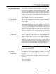
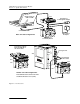
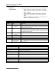
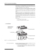
Table 2-1 Controls, Connectors, and Indicators – 2102 Module
Item No.
Fig. 2-1
Name Description
1 Communication
Connector
Upper communication port. The connection transfers data and 12 VDC power
to other modules. The port may also be used to connect attached modules to
a PC running Flowlink software.
2 Connector Caps Insert into unused communication connectors to terminate the network and
protect them from moisture damage. When communication connectors are in
use, the caps must be stowed as shown in Figure 2-1 to protect the terminat-
ing components inside the caps.
3 Communication
Indicator
Illuminates when the module is active.
4 Latch Release Push in to release the module from a stack.
5 Latch Push in to lock the module in a stack.
6 Serial Number Label In back - lists product ID and unit serial numbers.
7 Communication
Connector
Lower communication port. The connector transfers data and 12 VDC power
to other modules.
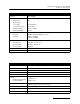
Table 2-2 Technical Specifications – 2102 Module
Size (H×W×D) 2.9 × 11.3 × 7.5 in. 7.4 × 28.7 × 19.1 cm
Weight 2.0 lbs 0.9 kg
Material High-impact molded polystyrene
Enclosure (self-certified) NEMA 4X, 6P IP 68
Power 10.2 to 16.6 VDC, 100 mA typical at 12 VDC, 1 mA standby
Typical Battery Life (one mod-
ule)
Typical: 50 days (when using two alkaline batteries)
Carrier Detect Cycle Time 4 minutes
Average Connection Time 2 minutes
Operating Temperature 0° to 140°F -18° to 60°C
Storage Temperature -40° to 140°F -40° to 60°C