2150EX Area Velocity Flow Module Installation and Operation Guide Part #69-2003-347 of Assembly #60-2004-347 Copyright © 2004. All rights reserved, Teledyne Isco, Inc.
Foreword This instruction manual is designed to help you gain a thorough understanding of the operation of the equipment. Teledyne Isco recommends that you read this manual completely before placing the equipment in service. Although Teledyne Isco designs reliability into all equipment, there is always the possibility of a malfunction. This manual may help in diagnosing and repairing the malfunction. If the problem persists, call or e-mail the Teledyne Isco Technical Service Department for assistance.
2150EX Area Velocity Flow System Safety Information 2150EX Area Velocity Flow System Safety Information General Warnings Before installing, operating, or maintaining this equipment, you should read this entire manual. While specific hazards may vary according to location and application, it is still helpful to read this safety section (which is specific to the 2150EX) and the general safety information contained in Appendix E.
2150EX Area Velocity Flow System Safety Information Hazard Symbols The equipment and this manual use symbols to warn of hazards. The symbols are explained below. Hazard Symbols Warnings and Cautions The exclamation point within the triangle is a warning sign alerting you of important instructions in the instrument’s manual. The lightning flash and arrowhead within the triangle is a warning sign alerting you of “dangerous voltage” inside the product.
2150EX Area Velocity Flow System Safety Information 2150EX Module Connected to 2191EX Battery Module and AV2150EX Sensor Installation should be completed with adherence to local requirements for ATEX Group II, Category 1G or 2G equipment as appropriate, and should be done by trained and qualified personnel.
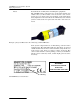
2150EX Area Velocity Flow System Safety Information Labels Read all labels carefully before installing the equipment! The 2150EX and its components are clearly labeled with color and/or text so you know what can be located in a safe or hazardous area (see figure below). For example, on the label shown below, light blue is used to indicate the intrinsically safe end and yellow to indicate the non-protected end of the cable and connector.
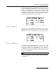
2150EX Area Velocity Flow System Safety Information Where applicable, the labels contain other information, such as voltage, serial number identification, etc. For example, the label shown below indicates the maximum input voltage (Ui), input current (I i ), and input power (P i ) that can be applied to the 2150EX network port without invalidating intrinsic safety. It also shows the internal capacitance (Ci), and internal inductance (Li) that must be allowed by any power source.
2150EX Area Velocity Flow System Safety Information Installation Installation of the 2150EX system is described in this manual. Typical round-pipe installations are shown in Figures 2-1 and 2-2, and Appendix E provides information on general safety procedures for work in manholes and sewers. When the equipment is installed in accordance with the instructions in this manual, it will not be subjected to dangerous mechanical or thermal stresses.
2150EX Area Velocity Flow System Table of Contents Section 1 Introduction 1.1 Product Description. . . . . . . . . . . . . . . . . . . . . . . . . . . . . . . . . . . . . . . . . . . . . . . . . . 1.1.1 2150EX Area Velocity Flow System Overview . . . . . . . . . . . . . . . . . . . . . . . 1.1.2 Level . . . . . . . . . . . . . . . . . . . . . . . . . . . . . . . . . . . . . . . . . . . . . . . . . . . . . . . . 1.1.3 Velocity . . . . . . . . . . . . . . . . . . . . . . . . . . . . . . . . . . . . . . . . .
2150EX Area Velocity Flow System Table of Contents 3.3 Program Settings. . . . . . . . . . . . . . . . . . . . . . . . . . . . . . . . . . . . . . . . . . . . . . . . . . . . 3.3.1 Level . . . . . . . . . . . . . . . . . . . . . . . . . . . . . . . . . . . . . . . . . . . . . . . . . . . . . . . . 3.3.2 Zero Level Offset . . . . . . . . . . . . . . . . . . . . . . . . . . . . . . . . . . . . . . . . . . . . . . 3.3.3 No Velocity Data and Flow Rates . . . . . . . . . . . . . . . . . . . . . . . . . . . . . .
2150EX Area Velocity Flow System Table of Contents D.2 Planning . . . . . . . . . . . . . . . . . . . . . . . . . . . . . . . . . . . . . . . . . . . . . . . . . . . . . . . . . . D-2 D.3 Adverse Atmospheres. . . . . . . . . . . . . . . . . . . . . . . . . . . . . . . . . . . . . . . . . . . . . . . . D-2 D.4 Entering Manholes . . . . . . . . . . . . . . . . . . . . . . . . . . . . . . . . . . . . . . . . . . . . . . . . . . D-2 D.4.1 Traffic Protection . . . . . . . . . . . . . . . . . . . . . . . . . . .
2150EX Area Velocity Flow System Table of Contents List of Tables 1-1 1-2 1-3 1-4 1-5 1-6 1-7 1-8 1-9 3-1 4-1 4-2 4-3 D-1 14 2150EX Area Velocity Flow Module - Top and Bottom Views . . . . . . . . . . . . . . . . 1-4 2150EX Area Velocity Flow Module - Top Right View . . . . . . . . . . . . . . . . . . . . . 1-5 Components – AV2150EX Area Velocity Sensor . . . . . . . . . . . . . . . . . . . . . . . . . . 1-6 Battery Components - 2191EX and 2196EX . . . . . . . . . . . . . . . . . . . . . . . . . . . . .
2150EX Area Velocity Flow Module Section 1 Introduction 1.1 Product Description The 2150EX Area Velocity Flow Module is part of Isco’s 2100 Series. The 2100 Series measures parameters of open channel flow streams. The intrinsically safe 2150EX is intended for use in potentially explosive atmospheres, and complies with ATEX Directive 94/9/EC. The 2150EX is Group II, Category 1G or 2G equipment as appropriate for use in Hazardous Zones 0, 1, and 2.
2150EX Area Velocity Flow Module Section 1 Introduction 1.1.1 2150EX Area Velocity Flow System Overview AV Module The 2150EX is designed to provide durable operation with only a minimal amount of routine maintenance, all of which may be performed in the field, while keeping in mind restrictions for potentially explosive atmospheres. Typically, the 2150EX and its AV2150EX Sensor will only require that you keep the stream free from excessive debris, and replace or recharge spent desiccant and batteries.
2150EX Area Velocity Flow Module Section 1 Introduction Circuits internal to the module compare the frequencies of the sound waves and extract the difference. An increase or decrease in the frequency of the reflected wave indicates forward or reverse flow. The degree of change is proportional to the velocity of the flow stream. 1.1.4 Flow Rate Using measurements from the AV Sensor, the 2150EX can calculate the flow rate.
2150EX Area Velocity Flow Module Section 1 Introduction Whether the measurements are stored at the primary or secondary rate, they are stored in a rollover type of memory. When full, the module overwrites the oldest data with the newest readings. Rollover Memory 1.2 Identifying Module Components The various components of the 2150EX are shown in Figures 1-1 through 1-4. Items referenced in the figures are described in Tables 1-1 through 1-4.
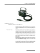
2150EX Area Velocity Flow Module Section 1 Introduction 1 2 3 4 5 Figure 1-2 2150EX Connected to 2191EX- Top Right View Table 1-2 2150EX Area Velocity Flow Module - Top Right View Item No. Fig. 2-2 Name Description 1 Carrying Handle 2 Communication Connector (shown capped) 3 Cap Holder 4 AV Sensor Receptacle 5 2191EX Used to lift and carry the unit. Upper communication port, used to connect to another module or to a PC running Flowlink software. Used to store the connector cap.
2150EX Area Velocity Flow Module Section 1 Introduction 2 1 4 3 Figure 1-3 Components – AV2150EX Area Velocity Sensor Table 1-3 Components – AV2150EX Area Velocity Sensor Item No. Fig. 1-3 1-6 Name Description 1 Connector Cap 2 Connector 3 AV Sensor Body 4 Cable Protects the connector. When the connector is not in use, this cap must be in place to prevent damage to the connector pins and reference air tubing. Attaches to the AV Sensor receptacle on the 2150EX Module.
50EX Area Velocity Flow Module Section 1 Introduction 2191EX 2196EX 3 3 2 1 1 Figure 1-4 2191EX and 2196EX Battery Components Table 1-4 Battery Components - 2191EX and 2196EX Item No. Fig. 1-4 Name Description The quarter-turn door seals the battery cavity. 2191EX: Inside each door is a humidity indicator and a bag of desiccant to prevent internal moisture damage.
2150EX Area Velocity Flow Module Section 1 Introduction Table 1-5 Technical Specifications – 2150EX and 2191EX Modules (Zones 0, 1, and 2) Size (H×W×D) 2150EX connected to 2191EX 22.6 × 28.0 × 19.3 cm 8.9 × 11.0 × 7.6 in. Weight (without batteries) (with lithium battery packs) (with lead-acid battery packs) 3.00 kg 4.20 kg 7.10 kg 6.6 lb 9.2 lb 15.7 lb Material ABS plastic, stainless steel Enclosure (self-certified) NEMA 4X, 6P Power 7.0 to 9.
2150EX Area Velocity Flow Module Section 1 Introduction Table 1-6 Technical Specifications - 2196EX Battery Module (Zones 1 and 2) Size (HxWxD) 14.94 x 23.12 x 19.3 cm 5.88 x 9.13 x 7.6 in. Weight 5.77 kg 12.71 lb Enclosure (self-certified) NEMA 4X, 6P IP 68 Operating and Storage Temperature -40 °C to 60 °C -40 °F to 140 °F Power Output Nominal: 8 VDC Maximum: 9.28 VDC Charger Input Nominal: 13.5 to 14.7 volts Absolute Maximum: 20 volts, 2.
2150EX Area Velocity Flow Module Section 1 Introduction Table 1-8 Specifications – AV2150EX Area Velocity Sensor (Zones 0, 1, and 2) Materials Sensor Epoxy, chlorinated polyvinyl chloride (CPVC), stainless steel Cable Polyvinyl chloride (PVC), chlorinated polyvinyl chloride (CPVC), stainless steel Size (H×W×D) 1.9 × 3.3 × 15.2 cm 0.75 × 1.31 × 6.00 in. Cable Length 10.0 m Cable Diameter 0.9 cm 0.37 in. Weight (including cable) 1.02 kg 2.24 lbs 32.8 ft.
2150EX Area Velocity Flow Module Section 1 Introduction G A F E B D C Communications Port Figure 1-5 2150EX Area Velocity Flow System Communication Connector Pins Table 1-9 Communication Connector Pins Pin Name Description A NETA Network differential transceiver Data A B NETB Network differential transceiver Data B C VIN+ Positive power supply voltage input (+8 VDC nominal) D VIN– Negative power supply voltage input (0 VDC nominal) E RCVUP PC data receiver RS232 compatible input F
2150EX Area Velocity Flow Module Section 1 Introduction 1-12
2150EX Area Velocity Flow Module Section 2 Preparation and Installation 2.1 Unpacking Instructions When the system arrives, inspect the outside packing for any damage. Then carefully inspect the contents for damage. If there is damage, contact the delivery company and Teledyne Isco (or its agent) immediately. WARNING If there is any evidence that any items may have been damaged in shipping, do not attempt to install the unit. Please contact Teledyne Isco (or its agent) for advice. Teledyne Isco, Inc.
2150EX Area Velocity Flow Module Section 2 Preparation and Installation 2.2 Preparing for Installation A 2150EX flow system may be a portable installation, powered by a 2191EX or 2196EX battery module (described in Section 2.4), or a permanent installation, powered from the safe area by the 2194EX network interface module (described in Section 2.5).
2150EX Area Velocity Flow Module Section 2 Preparation and Installation Note Primary devices limit the usefulness of the AV Sensor’s readings. In most cases, levels and velocities near these structures do not represent what normally occurs in the channel. If you must use area velocity flow conversion, or if your interest is the stream’s velocity, do not install the AV Sensor near a primary device. Move the AV Sensor away to where the flow is unaffected by the primary device. 2.2.
2150EX Area Velocity Flow Module Section 2 Preparation and Installation 2.3 Site Examples Figures 2-1, 2-2, and 2-3 illustrate typical round-pipe sites. Key items are called out in the illustration and explained below. Figures 2-1 and 2-2 represent portable installations. For details about portable installations, see Section 2.4. Figure 2-3 represents a permanent installation. For details about permanent installations, see Section 2.5.
2150EX Area Velocity Flow Module Section 2 Preparation and Installation Computer running Flowlink SAFE AREA LLY EXPLOSIVE AREA POTENTIA RS232EX Isolator Cable EX Network Cable (Hazardous boundaries are normally specified by local authorities.) 2150EX Area Velocity Flow Module 2191EX or 2196EX Battery Module Mounting Ring FLOW AV2150EX Sensor Figure 2-1 Typical Round-pipe Installation Connected to a Laptop Computer (Portable Installation, see section 2.
2150EX Area Velocity Flow Module Section 2 Preparation and Installation SAFE AREA LLY EXPLOSIVE AREA POTENTIA (Hazardous boundaries are normally specified by local authorities.) 2101 Field Wizard Module RS485EX Isolator Cable EX Network Cable 2150EX Area Velocity Flow Module 2191EX or 2196EX Battery Module Mounting Ring FLOW Figure 2-2 Typical Round-pipe Installation Connected to a 2101 Field Wizard (Portable Installation, see section 2.
2150EX Area Velocity Flow Module Section 2 Preparation and Installation Equipment Box Computer running Flowlink Interrogator Cable 2194EX Network/ Power Module Isco Power Pack SAFE AREA EX Interface Cable and Conduit POTENTIALLY EXPLOSIVE AREA (Hazardous boundaries are normally specified by local authorities.) 2150EX Area Velocity Flow Module This figure is not intended to depict the meeting of special conditions indicated by "X" markings on the equipment. Refer to IEC 60079-14 section 12.2.
2150EX Area Velocity Flow Module Section 2 Preparation and Installation WARNING The sensor mounting ring is a potential isolated charge carrier. Your installation MUST satisfy earthing requirements. Refer to IEC 60079-14 section 12.2.4 and IEC 60079-11. 2.4 Portable Installations For portable installations, the 2150EX module is stacked with a 2191EX or 2196EX battery module.
2150EX Area Velocity Flow Module Section 2 Preparation and Installation Battery Pack Door Figure 2-4 Illustration of Battery Packs Figure 2-5 Label Markings for LTC2191EX and SLA2191EX Battery Packs CAUTION To avoid overloading the fuses in the LTC2191EX lithium battery packs, disconnect the 2150EX module(s) before installing or replacing the lithium battery packs. The SLA2191EX lead-acid battery packs do not contain fuses, and do not require that the 2150EX module(s) be disconnected.
2150EX Area Velocity Flow Module Section 2 Preparation and Installation If you are installing the LTC2191EX lithium battery packs, first disconnect the 2150EX module(s). If you are installing the SLA2191EX lead-acid battery packs, it is not necessary to disconnect the 2150EX module(s). Then: 1. Remove the battery door. To remove the door, turn it 1/4 turn counter-clockwise and pull it from the Battery Module. 2. Align the connectors and insert the new battery pack into the Battery Module. 3.
2150EX Area Velocity Flow Module Section 2 Preparation and Installation 2.4.5 Assembling the System Connection options The 2100 Series System is modular; you build the system by connecting modules together. The instructions in this section describe how to connect a 2150EX module to a 2191EX or 2196EX battery module in its most basic configuration — by stacking the two modules. The battery module must be at the bottom of the stack. You can use multiple modules in a stack to increase the site’s functions.
2150EX Area Velocity Flow Module Section 2 Preparation and Installation b. Coat the O-ring’s sealing surface with a silicone lubricant. (A small quantity of lubricant is supplied in the maintenance kit.) CAUTION Do not use petroleum-based lubricants. Petroleum-based lubricants will cause the O-ring to swell and eventually deteriorate. Aerosol silicone lubricant sprays often use petroleum based propellants.
2150EX Area Velocity Flow Module Section 2 Preparation and Installation 2.4.6 Zone 1 Battery Module The Model 2196EX is a rechargeable battery module for zones 1 and 2 that offers indication of declining voltage prior to power interruption, with two batteries permanently contained in an IP68 enclosure. See Figure 2-10 for X marking and port labeling. The 2196EX may be safely connected to or disconnected from a 2150EX flow module within a hazardous area.
2150EX Area Velocity Flow Module Section 2 Preparation and Installation Figure 2-7 Flowlink low-voltage warning CAUTION A 2196EX module kept in storage for extended periods should be recharged approximately every six to nine months. The battery voltage should never be allowed to fall below 10.5 volts before recharging. Deep discharge of the lead-acid batteries can lead to permanent loss of capacity.
2150EX Area Velocity Flow Module Section 2 Preparation and Installation The charging terminals are located on the circuit board mounted on the inside of the left compartment door (Figures 2-8 and 2-9, + and –). A cable ending in alligator clips may be connected to these terminals for charging. CAUTION The circuit board is permanently connected to the interior of the module. Use care when opening the case that the wires are not damaged.
2150EX Area Velocity Flow Module Section 2 Preparation and Installation Measure the voltage between Test Point 1 and H5 (negative terminal). 2A replaceable fuse BATTERY VOLTS (TP1) MAXIMUM 50 CELSIUS AMBIENT DURING CHARGE NEVER CHARGE IN POTENTIALLY EXPLOSIVE ENVIRONMENT FUSED INPUT VOLTAGE (LED) (-) NEGATIVE MAXIMUM CHARGER RATING 20 VOLTS 2 AMPERES Um = 250V Un = 20V (+) POSITIVE H19 Back Front There is a 60K ohm resistor in series with the voltage sensing circuit.
2150EX Area Velocity Flow Module Section 2 Preparation and Installation The 963 is a float mode charger, using a lower voltage, which reduces the risk of overcharging. It can fully charge the module in 16-24 hours maximum. Teledyne Isco also offers a 2-Amp charger that includes a connect cable ending in alligator clips, indicator lights for maximum output and float voltage, and protection against reverse polarity. It can charge the 2196EX to in about 6 hours.
2150EX Area Velocity Flow Module Section 2 Preparation and Installation 2.5 Permanent Installations For permanent installations, the 2150EX can be powered from a safe area by an associated apparatus, the 2194EX module. The 2194EX also serves as a network interface, with network and RS232 communication via the top connector.
2150EX Area Velocity Flow Module Section 2 Preparation and Installation Observe intrinsic safety requirements regarding proximity to external sources of potential electric or magnetic interference. Refer to IEC 10079-14 section 12.2.2.5 on installation of cables and wiring. WARNING Do not coil the interface cable; this will form an inductor and create a hazard. The cable should be kept as short as is practical.
2150EX Area Velocity Flow Module Section 2 Preparation and Installation %8 .%47/2+ 0/24 * 2194EX Network Connector 5O 6 )O ! 0O 7 #O U& ,O UH ,O 2O U( OHM Refer to page vi regarding "X" marking on labels. Figure 2-12 2194EX labels and cable connector Locking Socket ring insert Locking cap Main body Gland Gland cage Gland nut (When using conduit, replace with appropriate conduit fitting.) ).42).3)#!,,9 3!&% #)2#5)4 #ABLE 0IN #/..%#4/2 7()4% '2%%.
2150EX Area Velocity Flow Module Section 2 Preparation and Installation 1/2” NPT (20MM) Thread 1” NPT (32MM) Thread Figure 2-14 Network cable conduit fittings WHT/GRN WH N/ OR T WH 2 6 N/ GR T 1 W /BL U /O HT 3 5 WH T RN 7 Drain 4 BLU/WHT Figure 2-15 Wiring the socket insert 2.
2150EX Area Velocity Flow Module Section 2 Preparation and Installation 2.6.1 EX Network Cable The EX Network cable (2m P/N 60-2004-335, 8m P/N 60-2004-336) connects to the top of the 2150EX stack and extends to the interface of the safe and hazardous areas, where the actual isolation is located. Connects to a 2150EX Connects to an RS232EX or RS485EX Isolator Cable Figure 2-16 EX Network Cable for Connection to an Isolator Cable To connect the EX Network and RS232EX isolator cables: 1.
2150EX Area Velocity Flow Module Section 2 Preparation and Installation CAUTION Caps PUSH ON and PULL OFF. Do not rotate the caps to remove them from the connectors. 2.6.2 Connecting to a Computer for Interrogation The 2150EX module can be connected to a computer located in a safe area, using Isco’s Flowlink software (see Figure 2-1). In order for the 2150EX to communicate with a computer, the two must be connected by an Isco RS232EX Isolator Cable (P/N 60-2004-339).
2150EX Area Velocity Flow Module Section 2 Preparation and Installation Series network device other than the 2194EX, the two must be connected by an Isco RS485EX Isolator Cable (P/N 60-2004-340). The hazardous area end, labeled with proper entity parameters, connects to the EX Network cable. Observe intrinsic safety requirements regarding proximity to external sources of potential electric or magnetic interference. Refer to IEC 10079-14 section 12.2.2.5 on installation of cables and wiring.
2150EX Area Velocity Flow Module Section 2 Preparation and Installation Use care, so you do not misalign the pins and cause any short circuits! 4. Route the cable as shown in Figure 2-2, so the other end of the EX Network cable is at the interface of the safe and hazardous areas. 5. Attach the hazardous area end (with yellow/blue label) of the RS485EX cable to the EX Network cable coming from the 2150EX.
2150EX Area Velocity Flow Module Section 2 Preparation and Installation Sensor Release Caps Figure 2-19 Connecting the AV Sensor 3. Align and insert the connector. The sensor release will click when the sensor connector is fully seated. Important Information Regarding "X" Marking 4. Connect the two caps together. The ATEX labeling on the sensor’s serial tag shows a number ending in "X".
2150EX Area Velocity Flow Module Section 2 Preparation and Installation 2.7.1 Positioning the AV Sensor Sensor installation is discussed in Section 2.8 of this manual. Consult your Isco Mounting Rings instruction manual for detailed hardware information. This section explains how to position the AV Sensor in flow streams. Several factors concerning the AV Sensor’s installation may affect your system’s performance.
2150EX Area Velocity Flow Module Section 2 Preparation and Installation Handle with care - Abusive handling will damage the AV Sensor. Although the AV Sensor will survive normal handling and installation, treat the sensor with reasonable care. The internal components cannot be repaired. CAUTION The vent tube inside the sensor cable must remain open. Do not kink the cable or overtighten the plastic ties while securing the cable. WARNING Do not coil the sensor cable.
2150EX Area Velocity Flow Module Section 2 Preparation and Installation 2.8.1 Spring Rings To install a spring ring, compress the ring, slip it inside the pipe, and then allow it to spring out to contact the inside diameter of the pipe. The inherent outward spring force of the ring firmly secures it in place. A typical self-expanding mounting ring (with a probe mounted on it) is shown in Figure 2-21. These mounting rings are available for use in pipes with inside diameters of 15.2 cm (6"), 20.
2150EX Area Velocity Flow Module Section 2 Preparation and Installation CAUTION Make sure the slots on the AV sensor carrier are completely pressed into the tabs on the ring. This is particularly important where there is any possibility of reverse flows, or where flows are of high velocity. If the AV sensor is not fully pressed into the mounting ring tabs, it might come loose in the stream, and could possibly be damaged or lost.
2150EX Area Velocity Flow Module Section 2 Preparation and Installation the entire assembly and tightens it inside the pipe. The scissors section contains a long bolt that increases the length of the section as it is tightened. The assembled scissors rings fit pipe diameters from 16" to 80". Secure the unit in place by tightening the scissors mechanism with a 5/8" socket wrench or other suitable tool. Ring sections are .040" thick half-hard 301 stainless steel sheet.
2150EX Area Velocity Flow Module Section 2 Preparation and Installation Scissors Assembly Extensions Base Section Tightening the scissors assembly expands the ring to press firmly against the pipe wall, securing the ring. Figure 2-22 Scissors Ring adjustment To prevent debris from catching on the probe cable, it is important to attach the cable to the mounting ring so it offers as little resistance to the flow as possible.
2150EX Area Velocity Flow Module Section 2 Preparation and Installation CAUTION Under no circumstances should you leave any extra length of sensor cable dangling freely in the flow stream where it could trap debris or become tangled. Use gloves and eye protection when assembling and installing the rings in a pipe. Though deburred, the edges of the stainless steel can cut if improperly handled. Please read the information on how best to install this device.
2150EX Area Velocity Flow Module Section 2 Preparation and Installation Note The 2150EX requires Flowlink 4.1 or later. If you require two minute data storage intervals, you will need version 4.16 or later. Refer to Section 3 and define the following properties: • Level - Enter a liquid level measurement to adjust the level readings from the AV Sensor. • Zero Level Offset – If the AV Sensor is not installed in the bottom-center of the channel, an offset distance must be entered.
2150EX Area Velocity Flow Module Section 3 Programming 3.1 Overview This section describes how to set up the operation of a 2150EX Area Velocity Flow Module using Isco’s Flowlink software. Note The 2150EX requires Flowlink 4.1 or later. If you require two minute data storage intervals, you will need version 4.16 or later. Detailed Flowlink instructions are beyond the scope of this manual. Flowlink’s operating instructions are available in a Windows Help format.
2150EX Area Velocity Flow Module Section 3 Programming An easy way to begin Flowlink communications with the site is to Quick Connect. As a default Flowlink setting, the Quick Connect dialog box opens when you start Flowlink. Click on the large 2100 Instruments button to connect. Flowlink will read the 2100 system information and try to match it with an existing site in the open database. If Flowlink cannot find a match for the connected site, it creates a new site in the database. 3.2.
2150EX Area Velocity Flow Module Section 3 Programming Data Storage Settings General Settings Changing a Setting 3.3.1 Level Measurement Location You should also check the Data Storage Rates while you are reviewing the program settings. You can view the storage rates on the Data Storage tab to ensure that pertinent types of data are being stored, and that the rates will provide a sufficient amount of data for your application. Refer to section 3.3.
2150EX Area Velocity Flow Module Section 3 Programming a D h Level (h) = D − a 3.3.2 Zero Level Offset In round pipes it is possible to measure the level without disturbing the stream surface. This method is preferred. Refer to the diagram in the margin. First measure the inside diameter of the pipe (D). Then measure the airspace (a) from the liquid surface to the peak of the inside diameter. Average this measurement if the surface is not calm.
2150EX Area Velocity Flow Module Section 3 Programming 3.3.3 No Velocity Data and Flow Rates Occasionally velocity readings are lost because either a flow stream does not contain enough reflective particles, or the sensor is covered with silt. These lost velocity readings are logged as a “No Data Code.” If the 2150EX is set up to use area velocity flow conversion, it is then unable to calculate the flow rate.
2150EX Area Velocity Flow Module Section 3 Programming Table 3-1 Flow Conversion Methods Conversion Type Area Velocity Level to Flow Size or Parameters Channel Shape Area × Velocity Round Pipe, U-Channel, Rectangular, Trapezoidal, Elliptical Level-to-area Data Points User-developed Table 3 to 50 data points Weir V-Notch Weir 22.
2150EX Area Velocity Flow Module Section 3 Programming If the selected flow conversion requires channel dimensions, actual channel measurements should be taken. Channel measurements are preferred over nominal values. Significant errors may be introduced if your measurements are inaccurate. The example below illustrates the importance of accurate measurements. Example: Nominal Pipe Diameter: Actual Pipe Diameter: Level Measured Near Outfall: Correct Level Measurement: 10 inches 10.25 inches 2.
2150EX Area Velocity Flow Module Section 3 Programming 3.3.7 Site Name The module is shipped with a default name so that it can immediately begin to communicate with Flowlink. You can change the site name to a more descriptive name on the Site Info tab in Flowlink. Keep in mind that the name must be unique among the other site names in the open Flowlink database. Site names can be up to 20 characters long. Any character may be used in the name except: / : ? < | 3.3.
2150EX Area Velocity Flow Module Section 4 Modbus Protocol Sections 4.1 through 4.5 give an overview of the basic capabilities and operation of Modbus protocol as it applies to Isco 2100 Series flow modules. For a Glossary of Terms and Common Acronyms, see sections 4.4 and 4.5. For Modbus technical specifications, turn to section 4.6. 4.1 Introduction Modbus is a simple command/response mechanism to read from and write to specific memory locations called registers.
2150EX Area Velocity Flow Module Section 4 Modbus Protocol By accessing these registers you can obtain the current value of whatever parameter you desire. The reading(s) can then be displayed or stored wherever you designate as a destination; for example, a process control computer. Note Level, flow, velocity, and temperature data is stored in metric units only. Not all registers are limited to read-only data storage. You can also use some registers for control purposes.
2150EX Area Velocity Flow Module Section 4 Modbus Protocol 4.3 Configurations A variety of configurations can be made with Modbus, either through direct connection or through a modem. In the example shown in Figure 4-1, you are direct-connecting a server PC to two individual 2150s through Modbus, using the COM ports on the OPC Server, which are directly connected to the remote 2150s. Connection to the module is made through the RS-232 communication port on the top of the module.
2150EX Area Velocity Flow Module Section 4 Modbus Protocol 5. OPC connects to the 2150 stack through the cable (direct connection), takes register data from the specified 2150, and populates the OPC server's holding index. 6. Process Control takes data from the OPC server's holding index and gives data to the user. Note that Process Control can be either manual or automated in this example, and that the OPC server and Process Control may be located physically on the same computer. 4.
2150EX Area Velocity Flow Module Section 4 Modbus Protocol SCADA systems can be relatively simple, such as one that monitors the environmental conditions of a small office building, or very complex, such as a system that monitors all the activity in a nuclear power plant or a municipal water system. 4.
2150EX Area Velocity Flow Module Section 4 Modbus Protocol 4.6 Register Specifications All numbers in the Modbus registers are stored most significant byte first. If the polling device has a byte ordering of least significant byte first (an Intel-based PC, for example), the bytes will need to be reversed after they are received. The Modbus ASCII address is used to index the data by modules. Modbus ASCII address 1 contains information related to the site.
2150EX Area Velocity Flow Module Section 4 Modbus Protocol The register definitions for the individual modules (Modbus ASCII addresses 2-(N+1)) are in Table 4-1 below: Table 4-2 Modbus ASCII Address 2-(N+1) Register Definitions Register Number(s) Name Data Type Units Read/Write 1-4 Model number 8-byte string None Read 5-23 Module name 38-byte string None Read 241 Identify module 16 bit integer None Read/Write 2 Take reading flag 16 bit integer None Read/Write 3 26 Update interval
2150EX Area Velocity Flow Module Section 4 Modbus Protocol Table 4-2 Modbus ASCII Address 2-(N+1) Register Definitions (Continued) Register Number(s) Name Data Type Units Read/Write (1) A write to the Identify module register will cause the module to perform the identify operation which may be a steady LED for a few seconds or a beep in the Field Wizard. (2) Setting the Take Reading flag to 1 will cause the module to update the registers with current data readings.
2150EX Area Velocity Flow Module Section 4 Modbus Protocol Table 4-2 Modbus ASCII Address 2-(N+1) Register Definitions (Continued) Register Number(s) Name Data Type Units Read/Write 238-243 Analog channel 5 time record Time 250,251 Analog channel 6 4-byte float 252 Analog channel 6 status code 16-bit integer Read 253-258 Analog channel 6 time record Time Read 265,266 Analog channel 7 4-byte float 267 Analog channel 7 status code 16-bit integer Read 268-273 Analog channel 7 time r
2150EX Area Velocity Flow Module Section 4 Modbus Protocol 4-10
2150EX Area Velocity Flow Module Section 5 Maintenance 5.1 Maintenance Overview This section explains the maintenance requirements of the 2150EX Area Velocity Flow Module, 2191EX Battery Module, and the AV2150EX Sensor. The 2150EX System is designed to perform reliably in adverse conditions with a minimal amount of routine service requirements. To keep your system working properly, the following should be checked at regular intervals: • Battery power (section 5.3) • Desiccant (section 5.
2150EX Area Velocity Flow Module Section 5 Maintenance 5.3 2191EX Batteries When connected to a 2191EX battery module, the 2150EX is powered by either two LTC2191EX 8 volt lithium battery packs or two SLA2191EX 8 volt lead-acid battery packs, which are stored in the 2191EX. These packs are sealed and explosion protected, so they can be safely removed and replaced in a potentially explosive atmosphere.
2150EX Area Velocity Flow Module Section 5 Maintenance WARNING Substitution of components may impair intrinsic safety. WARNING To avoid overloading the fuses in the lithium LTC2191EX battery packs, disconnect the 2150EX module(s) before installing or replacing battery packs. Battery Pack Door Figure 5-1 Illustration of LTC2191EX Battery Packs To install the lithium LTC2191EX battery packs, first disconnect the 2150EX module(s) and then: 1. Remove the battery door.
2150EX Area Velocity Flow Module Section 5 Maintenance Note For storage, the battery packs may be rotated 180 degrees and inserted into the 2191EX. This disconnects the packs for storage. 5.3.2 SLA2191EX Lead-Acid Batteries The lead-acid battery packs should give you several weeks of service before they need recharged, depending upon your data storage intervals (see Table 1-5 and Figure 5-2).
2150EX Area Velocity Flow Module Section 5 Maintenance CAUTION Do not deep discharge the SLA2191EX battery packs, or you will reduce their cycle life. When your Flowlink voltage readings start to drop, you should recharge the battery packs. Charging Batteries Charge the batteries only with Isco’s 8V2191SLA Lead-Acid Battery Charger, P/N 60-2004-343 (Figure 5-3). The maximum ambient temperature when charging is 50°C or 122°F.
2150EX Area Velocity Flow Module Section 5 Maintenance Figure 5-4 Inserting an SLA2191EX Battery Pack into the Charger It will typically take two days for the green LED to go out, and it is recommended that you continue charging for another 24 to 48 hours after the green LED light goes out. The battery packs may remain in the powered charger indefinitely without damage. If stored for a long time, the SLA2191EX battery packs may self discharge to a point where they should be recharged.
2150EX Area Velocity Flow Module Section 5 Maintenance Installing SLA2191EX Battery Packs Battery Pack Door Figure 5-5 Illustration of Battery Packs To install the lead-acid SLA2191EX battery packs: 1. Remove the battery door. To remove the door, turn it 1/4 turn counter-clockwise and pull it from the Battery Module. 2. Align the connectors and insert the new battery pack into the Battery Module. 3. Check the humidity indicator disk inside the door. (See section 5.4.2.) 4. Replace the door.
2150EX Area Velocity Flow Module Section 5 Maintenance 5.4 Desiccant 30 20 40 Battery Module Humidity Indicator The 2150EX System devices use desiccant to protect the internal components from moisture damage. In the 2150EX, a desiccant cartridge is used to dry the reference air for the sensor. This prevents moisture from plugging the reference line, which would cause the sensor to report erroneous level readings. The cartridge is filled with indicating silica gel, which is blue or yellow when dry.
2150EX Area Velocity Flow Module Section 5 Maintenance 2. Rotate the retaining plate until it is free from the mounting screws. 3. Remove the spent desiccant bag from the cap and replace it with a new (P/N 099-0002-33) or reactivated (see section 5.4.3) bag. 4. Replace the retaining plate and secure it with the screws. 5.4.3 Reactivating the Desiccant Silica gel beads, granules, and bags of desiccant can be reactivated. CAUTION Desiccant may produce irritating fumes when heated.
2150EX Area Velocity Flow Module Section 5 Maintenance FROM DWG 60-2005-003 5.6.1 Hydrophobic Filter 5.6.2 Cleaning If the 2150EX is submerged, a hydrophobic filter prevents water from entering the desiccant cartridge and reference line. Any amount of water will plug the filter and it must be replaced so that the reference line can be reliably ventilated. Drifting level readings are often an indication that the hydrophobic filter may be plugged.
2150EX Area Velocity Flow Module Section 5 Maintenance 5.6.3 Sensor Cable Inspection Erroneous level or velocity readings may not always indicate a fault inside the AV Sensor body. A damaged cable can affect the operation of the sensor, particularly if the reference air tube inside the cable is collapsed or blocked. Damaged cables cannot be spliced or repaired. If the AV Sensor cable is damaged, you must replace the entire assembly, as the sensor body and cable are a factory-sealed unit.
2150EX Area Velocity Flow Module Section 5 Maintenance 5-12
2150EX Area Velocity Flow Module Appendix A Replacement Parts A.1 Replacement Parts Diagrams and Listings Replacement parts for the 2150EX, the Area Velocity Sensor, the 2191EX battery module, and the 2194EX interface module are called out in the diagrams in this appendix. Refer to the parts lists to determine the part number and description for a specific item. Replacement parts can be purchased by contacting Teledyne Isco’s Customer Service Department. Teledyne Isco, Inc. Customer Service Department P.
2150EX Area Velocity Flow Module Appendix A Replacement Parts A-2
2150EX Area Velocity Flow Module Appendix A Replacement Parts A-3
2150EX Area Velocity Flow Module Appendix A Replacement Parts A-4
2150EX Area Velocity Flow Module Appendix A Replacement Parts A-5
2150EX Area Velocity Flow Module Appendix A Replacement Parts A-6
2150EX Area Velocity Flow Module Appendix A Replacement Parts This page left intentionally blank.
2150EX Area Velocity Flow Module Appendix A Replacement Parts 602002331 A A-8
2150EX Area Velocity Flow Module Appendix A Replacement Parts A-9
2150EX Area Velocity Flow Module Appendix A Replacement Parts A-10
2150EX Area Velocity Flow Module Appendix A Replacement Parts A-11
2150EX Area Velocity Flow Module Appendix A Replacement Parts A-12
2150EX Area Velocity Flow Module Appendix A Replacement Parts A-13
2150EX Area Velocity Flow Module Appendix A Replacement Parts A-14
2150EX Area Velocity Flow Module Appendix A Replacement Parts A-15
2150EX Area Velocity Flow Module Appendix A Replacement Parts A-16
2150EX Area Velocity Flow Module Appendix A Replacement Parts A-17
2150EX Area Velocity Flow Module Appendix A Replacement Parts A-18
2150EX Area Velocity Flow Module Appendix B Accessories B.1 How to Order Accessories can be purchased by contacting Teledyne Isco’s Customer Service Department. Teledyne Isco, Inc. Customer Service Dept. P.O. Box 82531 Lincoln, NE 68501 USA Phone: (800) 228-4373 (402) 464-0231 FAX: (402) 465-3022 E-mail: IscoInfo@teledyne.com B.2 General Accessories AV2150EX Sensor (8m Cable) . . . . . . . . . . . . . . . . . . . 60-2004-331 Av2150EX Sensor (25m Cable) . . . . . . . . . . . . . . . . . .
2150EX Area Velocity Flow Module Appendix B Accessories 965 Five-Station Battery Charger . . . . . . . . . . . . . . . 68-3000-965 (US line cord; for use with 2196EX) 965 Five-Station Battery Charger . . . . . . . . . . . . . . . 69-3000-966 (EU line cord; for use with 2196EX) Alligator clip adaptor cable for 965 charger . . . . . . . . 60-1394-023 (for use with 2196EX) 963 Lead-Acid Battery Charger . . . . . . . . . . . . . . . . .
2150EX Area Velocity Flow Module Appendix C Material Safety Data Sheets C.1 Overview This appendix provides Material Safety Data Sheets for the desiccant used by the 2150EX Area Velocity Flow Module. Teledyne Isco cannot guarantee the accuracy of the data. Specific questions regarding the use and handling of the products should be directed to the manufacturer listed on the MSDS.
2150EX Area Velocity Flow Module Appendix C Material Safety Data Sheets 101 Christine Drive Belen, New Mexico 87002 Phone: (505) 864-6691 Fax: (505) 861-2355 ISO 9002 MATERIAL SAFETY DATA SHEET -- September 28, 1998 SORB-IT® Packaged Desiccant SECTION I -- PRODUCT IDENTIFICATION Trade Name and Synonyms: Chemical Family: Formula: Silica Gel, Synthetic Amorphous Silica, Silicon, Dioxide Synthetic Amorphous Silica SiO2.
2150EX Area Velocity Flow Module Appendix C Material Safety Data Sheets 101 Christine Drive Belen, New Mexico 87002 Phone: (505) 864-6691 Fax: (505) 861-2355 ISO 9002 MATERIAL SAFETY DATA SHEET -- September 28, 1998 SORB-IT® Packaged Desiccant SECTION IV -- FIRE EXPLOSION DATA Fire and Explosion Hazard - Negligible fire and explosion hazard when exposed to heat or flame by reaction with incompatible substances. Flash Point - Nonflammable. Firefighting Media - Dry chemical, water spray, or foam.
2150EX Area Velocity Flow Module Appendix C Material Safety Data Sheets 101 Christine Drive Belen, New Mexico 87002 Phone: (505) 864-6691 Fax: (505) 861-2355 ISO 9002 MATERIAL SAFETY DATA SHEET -- September 28, 1998 SORB-IT® Packaged Desiccant NOTE TO PHYSICIAN: This product is a desiccant and generates heat as it adsorbs water. The used product can contain material of hazardous nature. Identify that material and treat accordingly.
2150EX Area Velocity Flow Module Appendix C Material Safety Data Sheets 101 Christine Drive Belen, New Mexico 87002 Phone: (505) 864-6691 Fax: (505) 861-2355 ISO 9002 MATERIAL SAFETY DATA SHEET -- September 28, 1998 SORB-IT® Packaged Desiccant SECTION IX -- SPECIAL PRECAUTIONS Avoid breathing dust and prolonged contact with skin. Silica gel dust causes eye irritation and breathing dust may be harmful.
2150EX Area Velocity Flow Module Appendix C Material Safety Data Sheets Indicating Silica Gel Material Safety Data Sheet Identity (Trade Name as Used on Label) Manufacturer : MSDS Number* : MULTISORB TECHNOLOGIES, INC. M75 (formerly Multiform Desiccants, Inc.) Address: CAS Number* : 325 Harlem Road Buffalo, NY 14224 Phone Number (For Information): 716/824-8900 Emergency Phone 716/824-8900 Date Prepared: July 6, 2000 G.E.
2150EX Area Velocity Flow Module Appendix C Material Safety Data Sheets Page 2 Section 5 - Health Hazard Data PRIMARY ROUTES OF ENTRY HEALTH HAZARDS Inhalation Ingestion NTP CARCINOGEN LISTED IN Skin Absorption Not Hazardous IARC Monograph Acute May cause eye, skin and mucous membrane irritation. Chronic Prolonged inhalation may cause lung damage. OSHA Not Listed Signs and Symptoms Drying and irritation. of Exposure Medical Conditions Asthma.
2150EX Area Velocity Flow Module Appendix C Material Safety Data Sheets MATERIAL SAFETY DATA SHEET March 8, 2005 M163 Effective Date MSDS Number Section 1 – Product and Company Information Product Name: Silica gel, indicating, yellow Product Use: Grades: Synonyms: Desiccant, absorbent Silica gel, indicating Amorphous silica gel, SiO2, silicon dioxide (amorphous) Company; Street Address: City, State, Zip, Country: Multisorb Technologies, Inc.
2150EX Area Velocity Flow Module Appendix C Material Safety Data Sheets Section 4 – First Aid Measures Eyes: Rinse the eyes well with water while lifting the eye lids. If irritation persists, consult a physician. Skin: Wash affected area with soap and water. Ingestion: Ingestion is unlikely, this material will pass through the body normally. Inhalation: Remove the affected person to fresh air and get medical attention if necessary.
2150EX Area Velocity Flow Module Appendix C Material Safety Data Sheets Section 8 – Exposure Controls/Personal Protection Use exhaust ventilation to keep the airborne concentrations below the exposure limits. Engineering Controls: Respiratory Protection: Use NIOSH approved respirator when the air quality levels exceed the TLV's. Skin Protection: Light gloves will protect against abrasion and drying of the skin. Eye Protection: Safety glasses.
2150EX Area Velocity Flow Module Appendix C Material Safety Data Sheets Section 11 – Toxicological Information This product and its components are not listed on the NTP or OSHA Carcinogen lists. Animal Toxicology Tests for DOT Hazard classification ( Tests Conducted on finely ground silica gel) 1 - hour LC50 (rat) > 2 mg / l 48 - hour oral LD50 (rat) est. > 31,600 mg / kg 48 - hour dermal LD50 (rabbit) est.
2150EX Area Velocity Flow Module Appendix C Material Safety Data Sheets Section 16 – Other Information HMIS – Hazardous Materials Identification System HMIS Rating Health 0 Flammability 0 Reactivity 0 0 - minimal hazard, 1 - slight hazard, 2 - moderate hazard, 3 - serious hazard, 4 - severe hazard This MSDS was prepared by: George E. Mckedy Senior Applications Development Specialist Multisorb Technologies, Inc.
2150EX Area Velocity Flow Module Appendix D General Safety Procedures The intrinsically safe 2150EX is intended for use in potentially explosive atmospheres, and complies with ATEX Directive 94/9/EC. The 2150EX is Group II, Category 1G or 2G equipment for use in gas hazard zones 0, 1, and 2. For safety information specific to the 2150EX, refer to the Safety Information section at the front of this manual. The safety of the personnel who use the 2150EX is a critical consideration.
2150EX Area Velocity Flow Module Appendix D General Safety Procedures This applies to hand tools as well as stones, gravel and other objects. • Sharp Edges–Sharp edges of items in or near a manhole may cause cuts or bruises. • Lifting Injuries–Unless proper tools are used to remove manhole covers, back injuries or injuries to hands or feet may result. D.
2150EX Area Velocity Flow Module Appendix D General Safety Procedures A person should never enter a manhole unless he is wearing personal safety equipment, including a safety harness and a hard hat. Two persons should be stationed at the surface continuously while anyone is working inside a manhole, to lift him out if he is overcome or injured. One man cannot lift an unconscious man out of a manhole.
2150EX Area Velocity Flow Module Appendix D General Safety Procedures D.4.4 Emergencies Every member of the crew should be instructed on procedures to be followed in cases of an emergency. It is the duty of each crew chief to have a list of emergency phone numbers, including the nearest hospital and ambulance service, police precinct, fire station, and rescue or general emergency number. D.4.
2150EX Area Velocity Flow Module Appendix D General Safety Procedures Whitney, oxygen is equal to 12.2%t. Many hikers go there, and to higher peaks as well. After adequate acclimation, they may climb to the top of Mt. Everest, where oxygen is equal to only 6.7%. “The lowest oxygen concentrations that I have observed in a sewer atmosphere was 13 percent. It was in a sealed chamber, near sea level, upstream from an inverted siphon on a metropolitan trunk. A man would be foolish to enter the chamber.
2150EX Area Velocity Flow Module Appendix D General Safety Procedures tions. A supposed safety device that is unreliable is worse than none at all. “Remember that the nose fails, too, when it comes to sensing dangerous concentrations of H2S. “Various other toxic gases have been mentioned in some publications. It is unlikely that any person has been asphyxiated in a sewer by any of those other gases, except possibly chlorine.
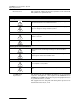
2150EX Area Velocity Flow Module Appendix D General Safety Procedures Table D-1 Hazardous Gases Gas Chemical Formula Common Properties Specific Gravity or Vapor Density Air = 1 Max Safe 60 Min. Exposure ppm Max. Safe 8 Hour Exposure ppm Ammonia NH3 Irritant and poisonous. Colorless with characteristic odor. 0.60 Causes throat and eye irritation at 0.05%, coughing at 0.17%. Short exposure at 0.5% to 1% fatal. 300 to 500 85 16 25 Near top.
2150EX Area Velocity Flow Module Appendix D General Safety Procedures Table D-1 Hazardous Gases (Continued) Gas Chemical Formula Common Properties Specific Gravity or Vapor Density Air = 1 Physiological Effect* Max Safe 60 Min. Exposure ppm Max. Safe 8 Hour Exposure ppm Hydrogen Sulfide H2S Irritant and poisonous volatile compound. Rotten egg odor in small concentrations. Exposure for 2 to 15 min. at 0.01% impairs sense of smell. Odor not evident at high concentrations. Colorless. Flammable. 1.
2150EX Area Velocity Flow System Index A L accessories, B-1 area velocity sensor cable, 5-11 connecting, 2-25 installation, 2-32 mounting, 2-28 positioning, 2-27 associated apparatus, 2-18 labeling, 1-8 level offset, 2-27, 3-4 B battery packs, 5-2 lead-acid, 5-4 lithium, 5-2 C communication, 2-21 component identification, 1-4 connector pins, 1-11 connector pins, 1-11 contact the factory, 5-11 D data storage, 1-3, 3-7 desiccant, 2-10, 5-8 F M maintenance channel conditions, 5-9 cleaning, 5-10 desicc
2150EX Area Velocity Flow System Index silt level, 3-7 site name, 3-8 R replacement parts, A-1 S safety, 1-5, 1-6, 1-7, 2-2, D-1 hazard severity levels, 1-5 hazard symbols, 1-6 installation, 1-10 labeling, 1-8 X-marking, 1-8, 2-17, 2-19, 2-26 scissors ring, 2-30 service, 5-11 diagnostics, 5-11 specifications, 1-7 stacking, 2-11 system assembly, 2-11 system overview, 1-2 T technical specifications, 1-7 total flow, 1-3 W warnings, 1-5 X X-marking, 1-8, 2-17, 2-19, 2-26 Index-2
DECLARATION OF CONFORMITY Application of Council Directive: Manufacturer's Name: Manufacturer's Address: Equipment Type/Environment: Trade Name/Model No: Year of Issue: Standards to which Conformity is Declared: EC-Type Examination Certificates: Flow Module Type 2150EX: Baseefa04ATEX0083 Sensor Type AV2150EX: Baseefa04ATEX0101X The 2150EX flow Monitoring System is covered by a QA Notification to Annex 4 of the 94/9/EC Directive issued by Baseefa NB number 1180.
Compliance Statements
DECLARATION OF CONFORMITY Manufacturer's Name: Manufacturer's Address: Equipment Type/Environment: Trade Name/Model No: Year of Issue: Standards to which Conformity is Declared: of C on EC-Type Examination Certificates: Battery Type LTC2191EX: Baseefa04ATEX0014 Battery Node Type2191EX: Baseefa04ATEX0013/1 Battery Type SLA2191EX: Baseefa04ATEX0339 Electrostatic Discharge EN61000-4-3 Severity Applied Performance Criteria Level 2 – 4Kv contact discharge Level 3 – 8Kv air discharge A A Radiated RF I
DECLARATION OF CONFORMITY Application of Council Directive: Manufacturer's Name: Manufacturer's Address: Equipment Type/Environment: ity Trade Name/Model No: Year of Issue: Standards to which Conformity is Declared: of C on fo r m EC-Type Examination Certificates: Interface Type 2194EX: Baseefa04ATEX0028X Description Electrostatic Discharge EN61000-4-3 Radiated RF Immunity EN61000-4-4 Severity Applied Performance Criteria Level 2 – 4Kv contact discharge Level 3 – 8Kv air discharge A A 80 MHz
DECLARATION OF CONFORMITY Application of Council Directive: Manufacturer's Name: Manufacturer's Address: Equipment Type/Environment: Trade Name/Model No: Year of Issue: Standards to which Conformity is Declared: EC-Type Examination Certificates: Isolator Cable Type RS232EX: Baseefa04ATEX0147 Isolator Cable Type RS485EX: Baseefa04ATEX0261 The 2150EX Flow Monitoring System is covered by a QA Notification to Annex 4 of the 94/9/EC Directive issued by Baseefa NB number 1180.
DECLARATION OF CONFORMITY Application of Council Directive: 2004/108/EC -The EMC Directive 94/9 EC - The ATEX Directive 2002/96/EC – The WEEE Directive Manufacturer's Name: Manufacturer's Address: Equipment Type/Environment: Trade Name/Model No: Year of Issue: Standards to which Conformity is Declared: EC-Type Examination Certificates: Battery Node Type 2196EX:Baseefa07ATEX0033X The 2150EX Flow Monitoring System is covered by a QA Notification to Annex 4 of the 94/9/EC Directive issued by Baseefa NB nu
Replacement Policy Although some repairs to the Teledyne Isco 2151, 2151P, 2150EX, and 2194EX modules can be made without opening the unit (such as problems with the battery component or firmware), there are some repairs that would require opening the unit. However, the Teledyne Isco 2151, 2151P, and 2150EX modules cannot be opened for repair without voiding their intrinsically safe certification.
arranty
Teledyne Isco One Year Limited Factory Service Warranty * Teledyne Isco warrants covered products against failure due to faulty parts or workmanship for a period of one year (365 days) from their shipping date, or from the date of installation by an authorized Teledyne Isco Service Engineer, as may be appropriate. During the warranty period, repairs, replacements, and labor shall be provided at no charge.