Percent Oxygen Analyzer OPERATING INSTRUCTIONS FOR Model 3000PA Percent Oxygen Analyzer DANGER HIGHLY TOXIC AND OR FLAMMABLE LIQUIDS OR GASES MAY BE PRESENT IN THIS MONITORING SYSTEM. PERSONAL PROTECTIVE EQUIPMENT MAY BE REQUIRED WHEN SERVICING THIS SYSTEM. HAZARDOUS VOLTAGES EXIST ON CERTAIN COMPONENTS INTERNALLY WHICH MAY PERSIST FOR A TIME EVEN AFTER THE POWER IS TURNED OFF AND DISCONNECTED. ONLY AUTHORIZED PERSONNEL SHOULD CONDUCT MAINTENANCE AND/OR SERVICING.
Model 3000PA Copyright © 1999 Teledyne Analytical Instruments All Rights Reserved. No part of this manual may be reproduced, transmitted, transcribed, stored in a retrieval system, or translated into any other language or computer language in whole or in part, in any form or by any means, whether it be electronic, mechanical, magnetic, optical, manual, or otherwise, without the prior written consent of Teledyne Analytical Instruments, 16830 Chestnut Street, City of Industry, CA 91749-1580.
Percent Oxygen Analyzer Specific Model Information The instrument for which this manual was supplied may incorporate one or more options not included with the standard instrument. Commonly available options are listed below, with check boxes. Any that are incorporated in the instrument for which this manual is supplied are indicated by a check mark in the box.
Model 3000PA Table of Contents 1 Introduction 1.1 1.2 1.3 1.4 1.5 1.6 1.7 Overview ........................................................................ 1-1 Typical Applications ....................................................... 1-1 Main Features of the Analyzer ....................................... 1-1 Model Designations ....................................................... 1-2 Front Panel (Operator Interface) .....................................
Percent Oxygen Analyzer 4.3.3.2 Installing or Changing the Password ............. 4-7 4.3.4 Logout .................................................................... 4-8 4.3.5 System Self-Diagnostic Test .................................. 4-9 4.3.6 Version Screen ...................................................... 4-9 4.4 The Zero and Span Functions ....................................... 4-10 4.4.1 Cell Failure ............................................................ 4-12 4.4.2 Span Cal .........
Model 3000PA DANGER COMBUSTIBLE GAS USAGE WARNING This is a general purpose instrument designed for usage in a nonhazardous area. It is the customer's responsibility to ensure safety especially when combustible gases are being analyzed since the potential of gas leaks always exist. The customer should ensure that the principles of operating of this equipment is well understood by the user.
Percent Oxygen Analyzer Introduction 1 Introduction 1.1 Overview The Teledyne Analytical Instruments Model 3000PA Percent Oxygen Analyzer is a versatile microprocessorbased instrument for detecting the percentage of oxygen in a variety of background gases. This manual covers the Model 3000PA General Purpose flush-panel and/or rack-mount units only. These units are for indoor use in a nonhazardous environment. 1.
1 Introduction Model 3000PA • Advanced Micro-Fuel Cell, designed for percent oxygen analysis. Several options are available. • Versatile analysis over a wide range of applications. • Microprocessor based electronics: 8-bit CMOS microprocessor with 32 kB RAM and 128 kB ROM. • Three user definable output ranges (from 0-1% through 0-100 %) allow best match to users process and equipment. • Air-calibration range for convenient spanning at 20.9 %.
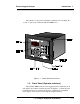
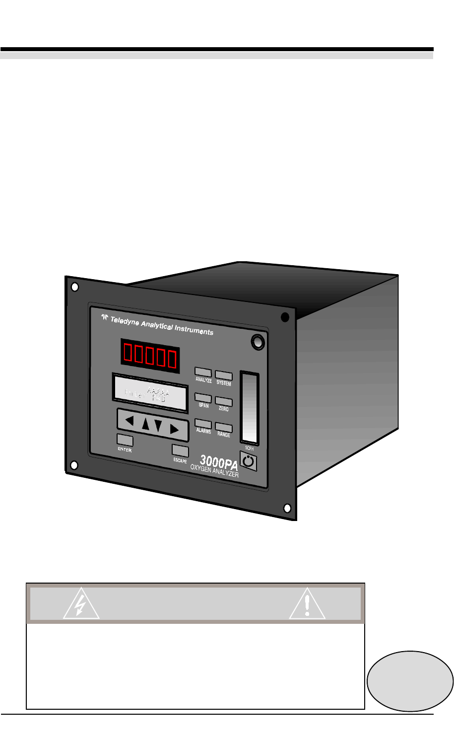
Percent Oxygen Analyzer Introduction 1 All of the above options are available in combination. For example, the -C and -V options are combined as Model 3000PA-C-V. Figure 1-1: Model 3000PA Front Panel 1.5 Front Panel (Operator Interface) The standard 3000PA is housed in a rugged metal case with all controls and displays accessible from the front panel. See Figure 1-1.
1 Introduction Model 3000PA Function Keys: Six touch-sensitive membrane switches are used to change the specific function performed by the analyzer: • Analyze Perform analysis for oxygen content of a sample gas. • System Perform system-related tasks (described in detail in chapter 4, Operation.). • Span Span calibrate the analyzer. • Zero Zero calibrate the analyzer. • Alarms Set the alarm setpoints and attributes. • Range Set up the 3 user definable ranges for the instrument.
Percent Oxygen Analyzer Introduction 1 Access Door: To provide access to the Micro-Fuel Cell, the front panel swings open when the latch in the upper right corner of the panel is pressed all the way in with a narrow gauge tool. Accessing the main circuit board requires unfastening the rear panel screws and sliding the unit out of the case. 1.6 Recognizing Difference Between LCD & VFD LCD has GREEN background with BLACK characters. VFD has DARK background with GREEN characters.
1 Introduction Model 3000PA • Alarm Connections 2 concentration alarms and 1 system alarm. • RS-232 Port Serial digital concentration signal output and control input. • Remote Probe Used in the 3000PA for controlling external solenoid valves only. • Remote Span/Zero Digital inputs allow external control of analyzer calibration. (See Note, below.) • Calibration Contact To notify external equipment that instrument is being calibrated and readings are not monitoring sample.
Percent Oxygen Analyzer Operational Theory 2 Operational Theory 2.1 Introduction The analyzer is composed of three subsystems: 1. Micro-Fuel Cell Sensor 2. Sample System 3. Electronic Signal Processing, Display and Control The sample system is designed to accept the sample gas and transport it through the analyzer without contaminating or altering the sample prior to analysis.
2 Operational Theory Model 3000PA analyzed. The Micro-Fuel Cell is therefore a hybrid between a battery and a true fuel cell. (All of the reactants are stored externally in a true fuel cell.) 2.2.2 Anatomy of a Micro-Fuel Cell The Micro-Fuel Cell is a cylinder only 1¼ inches in diameter and 1 inch thick. It is made of extremely inert plastic, which can be placed confidently in practically any environment or sample stream. It is effectively sealed, although one end is permeable to oxygen in the sample gas.
Percent Oxygen Analyzer Operational Theory 2 the oxygen sensing element—the cathode—with a surface area almost 4 cm2. The cathode has many perforations to ensure sufficient wetting of the upper surface with electrolyte, and it is plated with an inert metal. The anode structure is below the cathode. It is made of lead and has a proprietary design which is meant to maximize the amount of metal available for chemical reaction.
2 Operational Theory Model 3000PA (These reactions will hold as long as no gaseous components capable of oxidizing lead—such as iodine, bromine, chlorine and fluorine—are present in the sample.) The output of the fuel cell is limited by (1) the amount of oxygen in the cell at the time and (2) the amount of stored anode material. In the absence of oxygen, no current is generated. 2.2.
Percent Oxygen Analyzer Operational Theory 2 Figure 2-3. Characteristic Input/Output Curve for a Micro-Fuel Cell 2.2.6 Micro-Fuel Cell “Class” TBE manufactures Micro-Fuel Cells with a variety of characteristics to give the best possible performance for any given sample conditions. A few typical Micro-Fuel Cells are listed below with their typical use and electrical specifications. 2.2.6.
2 Operational Theory Model 3000PA Nominal output in air is 0.19 mA, and 90 % response time is 45 s. Expected life in flue gas is 8 months. 2.2.6.3 Class B-1 Cell The class B-1 cell is for use in applications where it is exposed to less than 0.1 % of carbon dioxide, and where fast response is important. Nominal output in air is 0.50 mA, and 90 % response time is 7 s. Expected life in air is 8 months. 2.2.6.
Percent Oxygen Analyzer Operational Theory 2 mizes residual gas pockets that can interfere with very low level oxygen analysis. The sample system for the standard instrument incorporates ¼ inch tube fittings for sample inlet and outlet connections at the rear panel. For metric system installations, 6 mm adapters are supplied with each instrument. The sample or calibration gas flow through the system is monitored by a flowmeter downstream from the cell.
2 Operational Theory Model 3000PA Span In Components in the shaded area are in the -C option (internal control valves) only and are not shown in the piping diagram above. Zero In Sample In Cell Solenoid Valves In vacuum service the restrictor should be placed here . In normal service the restrictor should be placed here . Flowmeter Exhaust Out Restrictor Figure 2-5: Flow Diagram 2.
Percent Oxygen Analyzer Operational Theory 2 The signal processing electronics including the microprocessor, analog to digital, and digital to analog converters are located on the motherboard at the bottom of the case. The preamplifier board is mounted on top of the motherboard as shown in the figure. These boards are accessible after removing the back panel. Figure 2-7 is a block diagram of the Analyzer electronics.
2 Operational Theory Model 3000PA In the presence of oxygen the cell generates a current. A current to voltage amplifier converts this current to a voltage, and then the voltage is amplified in the second stage amplifier. The second stage amplifier also supplies temperature compensation for the oxygen sensor output. This amplifier circuit incorporates a thermistor, which is physically located in the cell block.
Percent Oxygen Analyzer Installation 3 Installation Installation of the Model 3000PA Analyzer includes: 1. Unpacking 2. Mounting 3. Gas connections 4. Electrical connections 5. Installing the Micro-Fuel Cell 6. Testing the system. 3.1 Unpacking the Analyzer The analyzer is shipped with all the materials you need to install and prepare the system for operation. Carefully unpack the analyzer and inspect it for damage. Immediately report any damage to the shipping agent. 3.
3 Installation Model 3000PA 6.7” 10” Figure 3-1: Front Panel of the Model 3000PA All operator controls are mounted on the control panel, which is hinged on the left edge and doubles as the door that provides access to the sensor and cell block inside the instrument. The door is spring loaded and will swing open when the button in the center of the latch (upper right corner) is pressed all the way in with a narrow gauge tool (less than 0.
Percent Oxygen Analyzer Installation 3 Figure 3-3: Rear Panel of the Model 3000PA 3.3.1 Gas Connections Before using this instrument, it should be determined if the unit will be used for pressurized service or vacuum service and low pressure applications. Inspect the restrictor kit that came with the unit. The kit consist of two restrictors and a union for 1/4” diameter tubing. Notice that the two 1 3/4” long, 1/4” diameter tubing are restrictors.
3 Installation Model 3000PA The unit is manufactured with 1/4 inch tube fittings. Six millimeter adapters are supplied for metric system installations. For a safe connection: 1. Insert the tube into the tube fitting, and finger-tighten the nut until the tubing cannot be rotated freely, by hand, in the fitting. (This may require an additional 1/8 turn beyond finger-tight.) 2. Hold the fitting body steady with a backup wrench, and with another wrench rotate the nut another 1 1/4 turns.
Percent Oxygen Analyzer Installation 3 Primary Input Power: The power cord receptacle and fuse block are located in the same assembly. Insert the female plug end of the power cord into the power cord receptacle. CAUTION: Power is applied to the instrument's circuitry as long as the instrument is connected to the power source. The switch on the front panel is for switching power on or off to the displays and outputs only. The universal power supply requires a 85–250 V ac, 47-63 Hz power source.
3 Installation Model 3000PA Figure 3-4: Analog Output Connections Alarm Relays: The three alarm-circuit connectors are spring terminals for making connections to internal alarm relay contacts. Each provides a set of Form C contacts for each type of alarm. Each has both normally open and normally closed contact connections. The contact connections are indicated by diagrams on the rear panel. They are capable of switching up to 3 amperes at 250 V ac into a resistive load. See Figure 3-5.
Percent Oxygen Analyzer Installation 3 Digital Remote Cal Inputs: Accept 0 V (off) or 24 V dc (on) inputs for remote control of calibration. (See Remote Calibration Protocol below.) Zero: Floating input. A 5 to 24 V pulse input across the + and – terminals puts the analyzer into the Zero mode. Either side may be grounded at the source of the signal. A synchronous signal must open and close the external zero valve appropriately. See 3.3.3 Remote Probe Connector.
3 Installation Model 3000PA Note: The Remote Probe connector (paragraph 3.3.3) provides signals to ensure that the zero and span gas valves will be controlled synchronously. If you have the –C Internal valve option—which includes additional zero and span gas inputs— the 3000P automatically regulates the zero, span and sample gas flow. Range ID Relays: Four dedicated Range ID relay contacts.
Percent Oxygen Analyzer st Installation 3 Toggling input. Stops/Starts any status message output from the RS-232, until st is sent again. The RS-232 protocol allows some flexibility in its implementation. Table 3-2 lists certain RS-232 values that are required by the 3000PA implementation. Table 3-2: Required RS-232 Options Parameter Baud Byte Parity Stop Bits Message Interval Setting 2400 8 bits none 1 2 seconds 3.3.
3 Installation Model 3000PA Figure 3-7: FET Series Resistance 3.4 Installing the Micro-Fuel Cell The Micro-Fuel Cell is not installed in the cell block when the instrument is shipped. It must be installed before the analyzer is placed in service. Once it is expended, or if the cell is exposed to air for too long, the Micro-Fuel Cell will need to be replaced. The cell could also require replacement if the instrument has been idle for too long.
Percent Oxygen Analyzer Operation 4 Operation 4.1 Introduction Once the analyzer has been installed, it can be configured for your application. To do this you will: • • • • Set system parameters: • Establish a security password, if desired, requiring Operator to log in. • Establish and start an automatic calibration cycle, if desired. Calibrate the instrument. Define the three user selectable analysis ranges. Then choose autoranging or select a fixed range of analysis, as required.
4 Operation 4.2 Model 3000PA Using the Data Entry and Function Buttons Data Entry Buttons: The < > arrow buttons select options from the menu currently displayed on the VFD screen. The selected option blinks. When the selected option includes a modifiable item, the ∆∇ arrow buttons can be used to increment or decrement that modifiable item. The Enter button is used to accept any new entries on the VFD screen.
Percent Oxygen Analyzer Operation 4 Contrast Function is DISABLED (Refer to Section 1.6) Figure 4-1: Hierarchy of Functions and Subfunctions duced, at the appropriate point in the procedure, in a Monospaced type style. Pushbutton names are printed in Oblique type. 4.3 The System Function The subfuctions of the System function are described below. Specific procedures for their use follow the descriptions: • • Auto-Cal: Used to define an automatic calibration sequence and/or start an Auto-Cal.
4 Operation • • • • Model 3000PA operation, such as setting the instrument span or zero setting, adjusting the alarm setpoints, or defining analysis ranges. After a password is assigned, the operator must log out to activate it. Until then, anyone can continue to operate the instrument without entering the new password. Only one password can be defined. Before a unique password is assigned, the system assigns TBEAI by default. This allows access to anyone.
Percent Oxygen Analyzer Operation 4 4.3.2 Setting up an Auto-Cal When proper automatic valving is connected (see chapter 3, installation), the Analyzer can cycle itself through a sequence of steps that automatically zero and span the instrument. Note: If you require highly accurate Auto-Cal timing, use external Auto-Cal control where possible. The internal clock in the Model 3000PA is accurate to 2-3 %. Accordingly, internally scheduled calibrations can vary 2-3 % per day.
4 Operation Model 3000PA If you have decided not to employ password security, use the default password TBEAI. This password will be displayed automatically by the microprocessor. The operator just presses the Enter key to be allowed total access to the instrument’s features. NOTE: If you use password security, it is advisable to keep a copy of the password in a separate, safe location. 4.3.3.
Percent Oxygen Analyzer Operation 4 Change Password? =Yes =No Press Escape to move on, or proceed as in Changing the Password, below. 4.3.3.2 Installing or Changing the Password If you want to install a password, or change an existing password, proceed as above in Entering the Password.
4 Operation Model 3000PA AAAAA Retype PWD To Verify Wait a moment for the entry screen. You will be given clearance to proceed. AAAAA TO Proceed Use the arrow keys to retype your password and press Enter when finished. Your password will be stored in the microprocessor and the system will immediately switch to the Analyze screen, and you now have access to all instrument functions. If all alarms are defeated, the Analyze screen appears as: 0.
Percent Oxygen Analyzer Operation 4 4.3.5 System Self-Diagnostic Test The Model 3000PA has a built-in self-diagnostic testing routine. Preprogrammed signals are sent through the power supply, output board and sensor circuit. The return signal is analyzed, and at the end of the test the status of each function is displayed on the screen, either as OK or as a number between 1 and 3. (See System Self Diagnostic Test in chapter 5 for number code.
4 Operation 4.4 Model 3000PA The Span Functions The analyzer is calibrated using span gas. NOTE: Zero is not necessary for Percent (%) level measurements. Additional information on Zero functions is provided in the Appendix A-6 of this manual. Although the instrument can be spanned using air, a span gas with a known oxygen concentration in the range of 70–90% of full scale of the range of interest is recommended. Since the oxygen concentration in air is 20.
Percent Oxygen Analyzer Operation 4 Although the B-1 cell is standard in the 3000PA, check Specific Model Information in the Front Matter in this manual for the class of cell you purchased. Then check Cell Replacement in chapter 5 Maintenance, and do the prescribed calculations. If a weak cell is indicated, replace the cell as described there in chapter 5. 4.4.2 Span Cal The Span button on the front panel is used to span calibrate the analyzer.
4 Operation Model 3000PA of the displayed value of the oxygen concentration (in ppm) for three minutes. Then the instrument automatically returns to the analyze mode. 4.4.2.2 Manual Mode Spanning Press Span to start the Span function. The screen that appears allows you to select whether the span calibration is to be performed automatically or manually. Span: Settling:MAN For Next Use the ∆∇ keys to toggle between AUTO and MAN span settling. Stop when MAN appears, blinking, on the display.
Percent Oxygen Analyzer Operation 4 “C" contacts rated for 3 amperes resistive load at 250 V ac. See Figure in Chapter 3, Installation and/or the Interconnection Diagram included at the back of this manual for relay terminal connections. The system failure alarm has a fixed configuration described in chapter 3 Installation. The concentration alarms can be configured from the front panel as either high or low alarms by the operator.
4 Operation Model 3000PA The defeat function can also be used to reset a latched alarm. (See procedures, below.) If you are using password protection, you will need to enter your password to access the alarm functions. Follow the instructions in section 4.3.3 to enter your password. Once you have clearance to proceed, enter the Alarm function. Press the Alarm button on the front panel to enter the Alarm function. Make sure that AL–1 is blinking.
Percent Oxygen Analyzer 4.6 Operation 4 The Range Function The Range function allows the operator to program up to three concentration ranges to correlate with the DC analog outputs. If no custom ranges are defined by the user, the instrument defaults to: Low = 0–1.00 % Med = 0–5.00 % High = 0–10.00 %. The Model 3000PA is set at the factory to default to autoranging. In this mode, the microprocessor automatically responds to concentration changes by switching ranges for optimum readout sensitivity.
4 Operation Model 3000PA 4.6.2 Autoranging Analysis Set your analysis ranges as in 4.6.1, above. Leave Mode in Auto, or use the arrow buttons to change back to Auto. When operating in autoranging, if the oxygen concentration in your sample goes ABOVE your HIGHEST range setting, the analyzer will go into the special 25 % cal range. However, if one of your range settings is below 0-25 % and another is set above 0-25 %, the special 0-25 % Air Cal range will NOT activate as the oxygen level goes through 25 %.
Percent Oxygen Analyzer Operation 4 Press Escape to re-enter the Analyze mode using the fixed range. NOTE:When performing analysis on a fixed range, if the oxygen concentration rises above the upper limit (or default value) as established by the operator for that particular range, the output saturates at 1 V dc. However, the digital readout and the RS-232 output continue to read the true value of the oxygen concentration regardless of the analog output range. 4.
4 Operation Model 3000PA The analog output signal has a voltage which depends on the oxygen concentration AND the currently activated analysis range. To relate the signal output to the actual concentration, it is necessary to know what range the instrument is currently on, especially when the analyzer is in the autoranging mode. To provide an indication of the range, a second pair of analog output terminals are used.
Percent Oxygen Analyzer Maintenance 5 Maintenance 5.1 Routine Maintenance Aside from normal cleaning and checking for leaks at the gas connections, routine maintenance is limited to replacing Micro-Fuel cells and fuses, and recalibration. For recalibration, see Section 4.4 Calibration. WARNING: SEE WARNINGS ON THE TITLE PAGE OF THIS MANUAL. 5.2 Cell Replacement The Micro-Fuel Cell is a sealed electrochemical transducer with no electrolyte to change or electrodes to clean.
5 Maintenance Model 3000P LEAD AND POTASSIUM HYDROXIDE, THAT CAN BE HARMFUL IF TOUCHED, SWALLOWED, OR INHALED. AVOID CONTACT WITH ANY FLUID OR POWDER IN OR AROUND THE UNIT. WHAT MAY APPEAR TO BE PLAIN WATER COULD CONTAIN THESE TOXIC SUBSTANCES. IN CASE OF EYE CONTACT, IMMEDIATELY FLUSH EYES WITH WATER FOR AT LEAST 15 MINUTES. CALL PHYSICIAN. (SEE APPENDIX, MATERIAL SAFETY DATA SHEET.) CAUTION: Do not disturb the integrity of the cell package until the cell is to actually be used.
Percent Oxygen Analyzer Maintenance 5 3. Divide the raw output reading by the percent oxygen concentration of your span gas. If the quotient is less than the Index value for the cell class you are using, replace the cell. Table 5-1: Cell Indices Cell Class Index A-3 1.818 A-5 1.818 B-1 4.545 B-3 3.716 B-5 1.244 B-7 1.515 C-3 2.488 C-5 0.606 5.2.3 Removing the Micro-Fuel Cell The Micro-Fuel cell is located inside the nylon Probe behind the front panel. (See Figure 5-1.
5 Maintenance Model 3000P Figure 5-1: Removing or Installing a Micro-Fuel Cell 5-4 Teledyne Analytical Instruments
Percent Oxygen Analyzer Maintenance 5 5.2.4 Installing a New Micro-Fuel Cell CAUTION: Do not touch the sensing surface of the cell. It is covered with a delicate Teflon membrane that can leak if punctured. The sensor must be replaced if the membrane is damaged. 1. Place the Cell in the Probe with the sensing surface facing outward (toward the screen in the Cap). 2. Screw the Probe Cap onto the Probe until it stops. 3.
5 Maintenance 5.3 Model 3000P Fuse Replacement 1. Place small screwdriver in notch, and pry cover off, as shown in Figure 5-2. Figure 5-2: Removing Fuse Block from Housing 2. To change between American and European fuses, remove the single retaining screw, flip Fuse Block over 180 degrees, and replace screw. 3. Replace fuse as shown in Figure 5-3. 4. Reassemble Housing as shown in Figure 5-2. American Fuses European Fuses Figure 5-3: Installing Fuses 5.4 System Self Diagnostic Test 1.
Percent Oxygen Analyzer Maintenance 5 Table 5-1: Self Test Failure Codes Power 0 1 2 3 OK 5 V Failure 15 V Failure Both Failed Analog 0 1 2 3 OK DAC A (0–1 V Concentration) DAC B (0–1 V Range ID) Both Failed Preamp 0 1 2 3 5.5 OK Zero too high Amplifier output doesn't match test input Both Failed Major Internal Components The Micro-Fuel cell is accessed by unlatching and swinging open the front panel, as described earlier.
5 Maintenance Model 3000P X X X X X X X X Figure 5-4: Rear-Panel Screws To detach the rear panel, remove only the eight screws marked with an X. 5.6 Cleaning If instrument is unmounted at time of cleaning, disconnect the instrument from the power source. Close and latch the front-panel access door. Clean outside surfaces with a soft cloth dampened slightly with plain clean water. Do not use any harsh solvents such as paint thinner or benzene.
Percent Oxygen Analyzer 5.7 Maintenance 5 Troubleshooting Problem: Erratic readings of the Oxygen concentration as reported by the analyzer. Possible Cause: The analyzer may have been calibrated in an inaccurate fashion. Solution: Turn the analyzer off, then back on again. Press the System key when prompted by the analyzer "Press System for default Values". This will return the analyzer to its default settings in calibration and zero values. If erratic behavior continues replace the sensor.
5 Maintenance 5-10 Model 3000P Teledyne Analytical Instruments
Percent Oxygen Analyzer Appendix Appendix A-1 Model 3000PA Specifications Packaging: General Purpose • Flush panel mount (Standard). • Rack mount — Relay rack mounted to contain either one or two instruments in one 19" relay rack mountable plate (Optional). Sensor: Class B-1 Micro-Fuel Cell (standard). Others available. Cell Block: Nylon. 90 % Response Time: 10 seconds at 25 °C (77 °F). Ranges: Three user definable ranges from 0-1 % to 0-100 %, plus air calibration range of 0-25 %.
Appendix Model 3000PA Accuracy: ±2% of full scale at constant temperature. ±5% of full scale over operating temperature range, on factory default analysis ranges, once thermal equilibrium has been reached. Analog outputs: 0-1 V dc percent-of-range (Standard) 0-1 V dc range ID (Standard) 4-20 mA dc—isolated— percent-of-range (Optional) 4-20 mA dc—isolated— range ID (Optional) Dimensions: 19 cm high × 24.9 cm wide × 31 cm deep (5.96″ × 8.7″ × 12.2″).
Percent Oxygen Analyzer Appendix A-2 Recommended 2-Year Spare Parts List Qty Part Number Description 1 C62374 Back Panel Board 1 C62371-B Front Panel Board 1 C62368-B Percent Preamplifier Board 1* C62365-C Main Computer Board (std) 1* C62365-A Main Computer Board (4-20 mA) 3 F9 Fuse, 1 A, 250 V, 3 AG, Slow Blow 3 F1275 Fuse, 1 A, 250 V, 5 × 20 mm, Slow Blow 1 R1460 Molex Connector for Remote Probe 1 T976 Molex Crimp Terminals for Remote Probe Connector 2 O38 O-ring 1** C66
Appendix Model 3000PA A-3 Drawing List D-64573 Final Assembly/Outline Drawing A-4 19-inch Relay Rack Panel Mount Figure A-1: Single and Dual 19" Rack Mounts A-4 Teledyne Analytical Instruments
Percent Oxygen Analyzer A-5 Appendix 3000 SERIES ANALYZERS APPLICATION NOTES ON RESTRICTORS, PRESSURES, AND FLOW RECOMMENDATIONS 3000 series analyzers require reasonably regulated sample pressures. While the 3000 analyzers are not sensitive to variations of incoming pressure (provided they are properly vented to atmospheric pressure) The pressure must be maintained as to provide a useable flow rate trough the analyzer. Any line attached to sample vent should be 1/4 or larger in diameter.
Appendix Model 3000PA RESTRICTOR KIT The current revision of the 3000 series analyzers are supplied with a kit containing two restrictors and a union which are user installed. These parts supplied to give the end user more flexibility when installing the analyzer. The restrictor kit is suitable for high and low positive pressure applications as well as vacuum service ( atmospheric pressure sample) applications ( see manual for installation instructions).
Percent Oxygen Analyzer Appendix customer must supply a control valves (or restrictors) for any SPAN or ZERO gas source which is attached to the Auto-Cal ports. The valve should be adjusted to the same flow rate as the sample gas . When restrictors are used, the gas pressure must be adjusted to achieve the proper flow rate. OPERATION WITHOUT A RESTRICTOR DEVICE: Operation without a restrictor device is not recommend as mentioned above. A 3000PA without any flow restrictor device was tested on 11-19-97.
Appendix A-6 Model 3000PA Zero Cal The Zero button on the front panel is used to enter the zero calibration function. Zero calibration can be performed in either the automatic or manual mode. In the automatic mode, an internal algorithm compares consecutive readings from the sensor to determine when the output is within the acceptable range for zero. In the manual mode, the operator determines when the reading is within the acceptable range for zero.
Percent Oxygen Analyzer Appendix to toggle between AUTO and MAN zero settling. Stop when MAN appears, blinking, on the display. Zero: Settling: Man To Begin Press Enter to begin the zero calibration. After a few seconds the first of five zeroing screens appears. The number in the upper left hand corner is the first-stage zero offset. The microprocessor samples the output at a predetermined rate.