
User guide


Percent Oxygen Analyzer Installation 3
3-5Teledyne Analytical Instruments
connected to the cable shield, and it must be tightly
fastened to the analyzer with its fastening screws.
Ultimately, it is the installer who ensures that the
connections provide adequate EMI/RFI shielding.
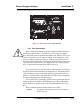
3.3.2.1 Primary Input Power
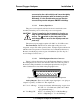
The power cord receptacle and fuse block are located in the same
assembly. Insert the power cord into the power cord receptacle.
CAUTION: Power is applied to the instrument's circuitry as
long as the instrument is connected to the power
source. The switch on the front panel is for
switching power on or off to the displays and out-
puts only.
The universal power supply requires a 85–250 V ac, 47-63 Hz source.
Fuse Installation: The fuse block, at the right of the power cord
receptacle, accepts US or European size fuses. A jumper replaces the fuse in
whichever fuse receptacle is not used. Fuses are not installed at the factory.
Be sure to install the proper fuse as part of installation. (See Fuse Replace-
ment in chapter 5, maintenance.)
3.3.2.2 50-Pin Equipment Interface Connector
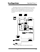
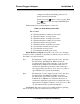
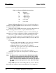
Figure 3-4 shows the pin layout of the Equipment Interface connector.
The arrangement is shown as seen when the viewer faces the rear panel of
the analyzer. The pin numbers for each input/output function are given
where each function is described in the paragraphs below.
Figure 3-4: Equipment Interface Connector Pin Arrangement
Analog Outputs: There are four DC output signal pins—two pins per
output. For polarity, see Table 3-1. The outputs are:
0–1 V dc % of Range: Voltage rises linearly with increasing oxygen, from
0 V at 0 % to 1 V at full scale. (Full scale = 100%
of programmable range.)
0–1 V dc Range ID: 0.25 V = Low Range, 0.5 V = Medium Range,
0.75 V = High Range, 1 V = Air Cal Range.