Oxygen Analyzer OPERATING INSTRUCTIONS Model 3010PAC Percent Oxygen Analyzer Flush Mount Control Unit, PN D-66192B CENELEC Type Remote Probe, PN B-39923C Intrinsic Safe Barriers Assy., PN C-66426 DANGER HIGHLY TOXIC AND OR FLAMMABLE LIQUIDS OR GASES MAY BE PRESENT IN THIS MONITORING SYSTEM. PERSONAL PROTECTIVE EQUIPMENT MAY BE REQUIRED WHEN SERVICING THIS SYSTEM. HAZARDOUS VOLTAGES EXIST ON CERTAIN COMPONENTS INTERNALLY WHICH MAY PERSIST FOR A TIME EVEN AFTER THE POWER IS TURNED OFF AND DISCONNECTED.
Model 3010PAC Copyright © 1999 Teledyne Analytical Instruments All Rights Reserved. No part of this manual may be reproduced, transmitted, transcribed, stored in a retrieval system, or translated into any other language or computer language in whole or in part, in any form or by any means, whether it be electronic, mechanical, magnetic, optical, manual, or otherwise, without the prior written consent of Teledyne Analytical Instruments, 16830 Chestnut Street, City of Industry, CA 917491580.
Oxygen Analyzer Table of Contents Specific Model Information .................................. iv Preface ................................................................ v Part I: Control Unit, Model PAC ............. Part I: 1-1 Part II: Intrinsic Safe Barriers ............... Part II: 1-1 Remote Probe ........................................... Appendix .........................................................
Model 3010PAC Specific Model Information The instrument for which this manual was supplied may incorporate one or more options not supplied in the standard instrument. Commonly available options are listed below, with check boxes. Any that are incorporated in the instrument for which this manual was supplied are indicated by a check mark in the box.
Oxygen Analyzer Preface Overview The Analytical Instruments Model 3010PAC Percent Oxygen Analyzer is a versatile microprocessor-based instrument for detecting oxygen in a variety of background gases. It is a “split architecture” instrument. This means that a general purpose Control Unit, designed for nonhazardous areas only, remotely controls a specially designed Analysis Unit, or remote probe, that can operate in a hazardous area.
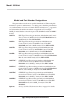
Model 3010PAC Model and Part Number Designations The part numbers are the most specific identification. When using this manual for operation, maintenance, or ordering parts, check the part numbers on your Instruments to be sure of a match. Where an underscore (_) appears in a model number, the unit has more than one application. For example, 3010P_C means that the same unit is part of the 3010PAC and the 3010PBC models. 3010TA: NEC Type Trace Oxygen Analyzer with flush mount Control Unit.
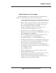
Oxygen Analyzer Main Features of the Analyzer The Model 3010PAC series Oxygen Analyzers are sophisticated yet simple to use. The main features of these analyzers include: • A 2-line alphanumeric display screen, driven by microprocessor electronics, that continuously prompts and informs the operator. • • • • • • • • • • • • • • High resolution, accurate readings of oxygen content: from low 0-1 % levels through 0-100 %. Large, bright, meter readout. Optional stainless steel cell block available.
Model 3010PAC Model 3010PAC complies with all of the requirements of the Commonwealth of Europe (CE) for Radio Frequency Interference, Electromagnetic Interference (RFI/EMI), and Low Voltage Directive (LVD). The Analysis Unit is Intrinsically safe and CENELEC approved. The Control Unit is suitable for general purpose areas. The probe is CENELEC approved (certification code EEXIA IICT6).
Part I: Control Unit OPERATING INSTRUCTIONS Models 3010PAC Oxygen Analyzer Part I Control Unit Flush Mount Part Number: D-66192B Teledyne Analytical Instruments Part I: i
Model 3010PAC Oxygen Analyzer Table of Contents 1 Introduction 1.1 1.2 1.3 1.4 Overview ........................................................................ 1-1 Control Unit Front Panel ................................................. 1-1 Recognizing Difference Between LCD & VFD ............... 1-3 Control Unit Rear Panel ................................................. 1-3 2 Operational Theory 2.1 Introduction .................................................................... 2-1 2.
Part I: Control Unit 4.3.4 Logout .................................................................... 4-8 4.3.5 System Self-Diagnostic Test .................................. 4-9 4.3.6 Version Screen ...................................................... 4-10 4.4 The Span Functions....................................................... 4-10 4.4.1 Cell Failurel ........................................................... 4-10 4.4.2 Span Cal ................................................................
Model 3010PAC Oxygen Analyzer iv: Part I Teledyne Analytical Instruments
Oxygen Analyzer Part I: Control Unit Introduction 1.1 Overview The Analytical Instruments Model 3010PAC Analyzer Control Unit, together with a 3010PAC Analysis Unit, is a versatile microprocessorbased instrument for detecting percent amounts of oxygen in a variety of gases. Part I, this part, of this manual covers the Model 3010PAC series General Purpose flush-panel and/or rack-mount Control Units. (The Analysis Unit is covered in Part II of this manual.
1 Introduction Model 3010PAC Figure 1-1: Front of Unmounted Control Unit Function Keys: Six touch-sensitive membrane switches are used to change the specific function performed by the analyzer: • Analyze Perform analysis for oxygen content of a sample gas. • System Perform system-related tasks (described in detail in chapter 4, Operation.). • Span Span calibrate the analyzer. • Zero Zero calibrate the analyzer. • Alarms Set the alarm setpoints and attributes.
Oxygen Analyzer Part I: Control Unit • Enter Moves VFD display on to the next screen in a series. If none remains, returns to the Analyze screen. • Escape Moves VFD display back to the previous screen in a series. If none remains, returns to the Analyze screen. Digital Meter Display: The meter display is a LED device that produces large, bright, 7-segment numbers that are legible in any lighting.
1 Introduction Model 3010PAC Figure 1-2: Model 3010PAC Rear Panel • Power Connection Universal AC power source. • Analog Outputs 0-1 V dc concentration and 0-1 V dc range ID. Optional isolated 4-20 mA dc and 4-20 mA dc range ID. • Alarm Connections 2 concentration alarms and 1 system alarm. • RS-232 Port Serial digital concentration signal output and control input. • Remote Probe Provides all electrical interconnect to the Analysis Unit or Remote Probe.
Oxygen Analyzer Part I: Control Unit • Remote Probe Interfaces with an Analysis Unit or Remote Probe (external sensor/sample system). • Network I/O Serial digital communications for local network access. For future expansion. Not implemented at this printing. Note: If you require highly accurate Auto-Cal timing, use external Auto-Cal control where possible. The internal clock in the Model 3010PAC is accurate to 2-3 %. Accordingly, internally scheduled calibrations can vary 2-3 % per day.
1 Introduction 1-6: Part I Model 3010PAC Teledyne Analytical Instruments
Oxygen Analyzer Part I: Control Unit Operational Theory 2.1 Introduction The Model 3010PAC Oxygen Analyzer Control Unit uses an 8031 microcontroller with 32 kB of RAM and 128 kB of ROM to control all signal processing, input/output, and display functions for the Model 3010PAC analyzer. (The sample system and Micro-Fuel Cell sensor are covered in Part II, Analysis Unit, in this manual.
2 Operational Theory Model 3010PAC Figure 2-1: Block Diagram of the 3010PAC CU Electronics 2-2: Part I Teledyne Analytical Instruments
Oxygen Analyzer Part I: Control Unit The digital concentration signal—along with input from the control panel—is processed by the microprocessor, and appropriate control signals are directed to the display, alarms and communications port as well as to the optional gas control valves in the Analysis Unit.
2 Operational Theory 2-4: Part I Teledyne Analytical Instruments Model 3010PAC
Oxygen Analyzer Part I: Control Unit Installation Installation of Model 3010PAC Analyzers includes: 1. Unpacking, mounting, and interconnecting the Control Unit and the Analysis Unit 2. Making gas connections to the system 3. Making electrical connections to the system 4. Testing the system. This chapter covers installation of the Control Unit. (Installation of the Analysis Unit is covered in Part II of this manual.) 3.
3 Installation Model 3010PAC Figure 3-1: Front Panel of the Model 3010 Control Unit Figure 3-2: Single and Dual 19" Rack Mounts All operator controls are mounted on the control panel, which is hinged on the left edge and doubles as a door to provide access to the internal components of the instrument.
Oxygen Analyzer Part I: Control Unit is pressed all the way in with a narrow gauge tool (less than 0.18 inch wide), such as a small hex wrench or screwdriver Allow clearance for the door to open in a 90-degree arc of radius 7.625 inches. See Figure 3-3. Figure 3-3: Required Front Door Clearance 3.3 Electrical Connections Figure 3-4 shows the Control Unit rear panel. Connections for power, communications, and both digital and analog signal outputs are described in the following paragraphs.
3 Installation Model 3010PAC CAUTION: Use Shielded Cables. Also, use plugs that provide excellent EMI/RFI protection. The plug case must be connected to the cable shield, and it must be tightly fastened to the analyzer with its fastening screws. Ultimately, it is the installer who ensures that the connections provide adequate EMI/RFI sielding. 3.3.1 Primary Input Power The universal power supply requires a 85–250 V ac, 47-63 Hz power source.
Oxygen Analyzer Part I: Control Unit Analog Outputs: There are four DC output signal pins—two pins per output. For polarity, see Table 3-1. The outputs are: 0–1 V dc % of Range: Voltage rises linearly with increasing oxygen, from 0 V at 0 ppm to 1 V at full scale ppm. (Full scale = 100% of programmable range.) 0–1 V dc Range ID: 0.25 V = Low Range, 0.5 V = Medium Range, 0.75 V = High Range, 1 V = Air Cal Range.
3 Installation Model 3010PAC • Can be configured as failsafe or nonfailsafe. • Can be configured as latching or nonlatching. • Can be configured out (defeated). Actuates when DC power supplied to circuits is unacceptable in one or more parameters. Permanently configured as failsafe and latching. Cannot be defeated. Actuates if self test fails. System Alarm: (Reset by pressing button to remove power. Then press again and any other button EXCEPT System to resume.
Oxygen Analyzer Part I: Control Unit synchronous signal must open and close external span valve appropriately. See Figure 3-5 Remote Probe Connector. (The –C option internal valves operate automatically.) Cal Contact: This relay contact is closed while analyzer is spanning and/or zeroing. (See Remote Calibration Protocol below.
3 Installation Model 3010PAC option—which includes additional zero and span gas inputs— the 3000PAC automatically regulates the zero, span and sample gas flow. Range ID Relays: Four dedicated Range ID relay contacts. The first three ranges are assigned to relays in ascending order— Low range is assigned to Range 1 ID, Medium range is assigned to Range 2 ID, and High range is assigned to Range 3 ID. The fourth range is reserved for the Air Cal Range (25%). Table 3-4 lists the pin connections.
Oxygen Analyzer Part I: Control Unit The voltage from these outputs is nominally 0 V for the OFF and 15 V dc for the ON conditions. The maximum combined current that can be pulled from these output lines is 100 mA. (If two lines are ON at the same time, each must be limited to 50 mA, etc.) If more current and/or a different voltage is required, use a relay, power amplifier, or other matching circuitry to provide the actual driving current.
3 Installation Model 3010PAC Table 3-5: Commands via RS-232 Input Command Description as Immediately starts an autospan. az Immediately starts an autozero. st Toggling input. Stops/Starts any status message output from the RS-232, until st is sent again. The RS-232 protocol allows some flexibility in its implementation. Table 3-6 lists certain RS-232 values that are required by the 3010PAC implementation.
Oxygen Analyzer Part I: Control Unit CAUTION: If you use your own control valves, or any other design, please be aware that the Intrinsic Safe requirements are provided. (See drawing D-66191 for wire recommendations). 3.4 Testing the System After The Control Unit and the Analysis Unit are both installed and interconnected, and the system gas and electrical connections are complete, the system is ready to test.
3 Installation 3-12: Part I Model 3010PAC Teledyne Analytical Instruments
Oxygen Analyzer Part I: Control Unit Operation 4.1 Introduction Once the analyzer has been installed, configure it for your process. To do this you can: • • • • Set system parameters— • Specify a password, if desired, requiring operator to log in. • Establish and start an automatic calibration cycle, if desired. Calibrate the instrument. Define the three user selectable analysis ranges. Then choose autoranging or select a fixed range of analysis, as required.
4 Operation Model 3010PAC 4.2 Using the Data Entry and Function Buttons Data Entry Buttons: The < > arrow buttons select options from the menu currently being displayed on the VFD screen. The selected option blinks. When the selected option includes a modifiable item, the ∆ ∇ arrow buttons can be used to increment or decrement that modifiable item. The Enter button is used to accept any new entries on the VFD screen.
Oxygen Analyzer Part I: Control Unit Contrast Function is DISABLED (Refer to Section 1.3) Figure 4-1: Hierarchy of Functions and Subfunctions Each of these functions is described in greater detail in the following procedures. The VFD screen text that accompanies each operation is reproduced, at the appropriate point in the procedure, in a Monospaced type style. Pushbutton names are printed in Oblique type. 4.3 The System Function The subfunctions of the System function are described below.
4 Operation • • • • Model 3010PAC activated, the operator MUST enter the UNIQUE password to gain access to set-up functions which alter the instrument's operation, such as setting the instrument span or zero setting, adjusting the alarm setpoints, or defining analysis ranges. After a password is assigned, the operator must log out to activate it. Until then, anyone can continue to operate the instrument without entering the new password. Only one password can be defined.
Oxygen Analyzer Part I: Control Unit 4.3.2 Setting up an Auto-Cal When the proper calibration gases are connected (see chapter 3, installation), the Analyzer can cycle itself through a sequence of steps that automatically zero and span the instrument. Note: If you require highly accurate Auto-Cal timing, use external Auto-Cal control where possible. The internal clock in the Model 3010PAC is accurate to 2-3 %. Accordingly, internally scheduled calibrations can vary 2-3 % per day.
4 Operation Model 3010PAC If you have decided not to employ password security, use the default password TBEAI. This password will be displayed automatically by the microprocessor. The operator just presses the Enter key to be allowed total access to the instrument’s features. NOTE: If you use password security, it is advisable to keep a copy of the password in a separate, safe location. 4.3.3.
Oxygen Analyzer Part I: Control Unit Change Password? =Yes =No Press Escape to move on, or proceed as in Changing the Password, below. 4.3.3.2 Installing or Changing the Password If you want to install a password, or change an existing password, proceed as above in Entering the Password.
4 Operation Model 3010PAC When you have finished typing the new password, press Enter. A verification screen appears. The screen will prompt you to retype your password for verification. AAAAA Retype PWD To Verify Wait a moment. The entry screen will give you clearance to proceed. AAAAA TO Proceed Use the arrow keys to retype your password and press Enter when finished.
Oxygen Analyzer Part I: Control Unit 4.3.5 System Self-Diagnostic Test The Model 3010PAC has a built-in self-diagnostic testing routine. Preprogrammed signals are sent through the power supply, output board and sensor circuit. The return signal is analyzed, and at the end of the test the status of each function is displayed on the screen, either as OK or as a number between 1 and 3. (See System Self Diagnostic Test in chapter 5 for number code.
4 Operation Model 3010PAC 4.3.6 Version Screen Move the < > arrow key to More and press Enter. With Version blinking, press Enter. The screen displays the manufacturer, model, and software version information. 4.4 The Span Functions The analyzer is calibrated using span gas. NOTE: Zero is not necessary for Percent (%) level measurements. Additional information on Zero functions is provided in the Appendix A-5 of this manual.
Oxygen Analyzer Part I: Control Unit Version Self—Test Cell Output: ### µA The “good” reading depends on the class of cell your analyzer is using. Although the B-1 cell is standard in the 3010PAC, check Specific Model Information in the Front Matter in this manual for the class of cell you purchased. Then check Cell Replacement in Part II Analysis Units, chapter 5 Maintenance, and do the prescribed calculations. If a weak cell is indicated, replace the cell as described there in chapter 5. 4.4.
4 Operation Model 3010PAC tion on Slope. Spanning automatically ends when the span output corresponds, within tolerance, to the value of the span gas concentration. Then the instrument automatically returns to the analyze mode. 4.4.2.2 Manual Mode Spanning Press Span to start the Span function. The screen that appears allows you to select whether the span calibration is to be performed automatically or manually.
Oxygen Analyzer 4.5 Part I: Control Unit The Alarms Function The Model 3010PAC is equipped with 2 fully adjustable concentration alarms and a system failure alarm. Each alarm has a relay with a set of form C contacts rated for 3 amperes resistive load at 250 V ac. See figure in chapter 3, Installation and/or the Interconnection Diagram included at the back of this manual for relay terminal connections. The system failure alarm has a fixed configuration described in chapter 3 Installation.
4 Operation Model 3010PAC The defeat alarm mode is incorporated into the alarm circuit so that maintenance can be performed under conditions which would normally activate the alarms. The defeat function can also be used to reset a latched alarm. (See procedures, below.) If you are using password protection, you will need to enter your password to access the alarm functions. Follow the instructions in Section 4.3.3 to enter your password. Once you have clearance to proceed, enter the Alarm function.
Oxygen Analyzer Part I: Control Unit Go to Ltch– and then press either ∆ two times or ∇ two times. (Toggle it to N and back to Y.) 4.6 The Range Function The Range function allows the operator to program up to three concentration ranges to correlate with the DC analog outputs. If no ranges are defined by the user, the instrument defaults to: Range Limits Low Med High 0–1 % 0–5 % 0–10 %. The Model 3010PAC is set at the factory to default to autoranging.
4 Operation Model 3010PAC Use the ∆∇ arrow keys to enter the upper value of the range (all ranges begin at 0 %). Repeat for each range you want to set. Press Enter to accept the values and return to Analyze mode. (See note below.) Note: The ranges must be increasing from low to high, for example, if range 1 is set for 0–10 % and range 2 is set for 0–100 %, range 3 cannot be set for 0–50 % since it is lower than range 2. 4.6.
Oxygen Analyzer 4.7 Part I: Control Unit The Analyze Function When the Analyze function is active, the 3010PAC is monitoring the sample gas currently flowing in the Analysis Unit cell block. All undefeated alarms are ready to activate should their respective setpoints be crossed. Press the Analyze button to put the analyzer in the Analyze mode. Normally, all of the functions automatically switch back to the Analyze function when they have completed their assigned operations.
4 Operation Model 3010PAC Interpretation of the analog output signal depends on the voltage (or current) AND the currently activated analysis range. To relate the signal output to the actual concentration, it is necessary to know what range the instrument is currently on, especially when the analyzer is in the autoranging mode. To provide an indication of the range, a second pair of analog output terminals are used.
Part I: Control Unit Maintenance 5 Maintenance Aside from normal cleaning and checking for leaks at the gas connections, routine maintenance is limited to replacing Micro-Fuel cells and fuses, and recalibration. Checking for leaks, replacing Micro-Fuel cells, and replacing fuses in the Analysis Unit are covered in Part II, Chapter 5. For recalibration, see Part I, section 4.4 Calibration. WARNING: SEE WARNINGS ON THE TITLE PAGE OF THIS MANUAL. 5.1 Fuse Replacement 1.
5 Maintenance Model 3010PAC Oxygen Analyzer 3. Replace fuse as shown in Figure 5-2. 4. Reassemble Housing as shown in Figure 5-1. American Fuses European Fuses Figure 5-2: Installing Fuses 5.2 System Self Diagnostic Test 1. Press the System button to enter the system mode. 2. Use the < > arrow keys to move to More, and press Enter. 3. Use the < > arrow keys to move to Self-Test, and press Enter.
Part I: Control Unit 5.3 Maintenance 5 Major Internal Components The major components in the Control Unit are shown in Figure 5-3. Figure 5-3: Control Unit Major Internal Components WARNING: HAZARDOUS VOLTAGES EXIST ON CERTAIN COMPONENTS INTERNALLY WHICH MAY PERSIST FOR A TIME EVEN AFTER THE POWER IS TURNED OFF AND DISCONNECTED.
5 Maintenance Model 3010PAC Oxygen Analyzer x x x x Figure 5-4: Rear-Panel Screws To detach the rear panel, remove only those four screws marked with an X. 5.4 Cleaning If instrument is unmounted at time of cleaning, disconnect the instrument from the power source. Close and latch the front-panel access door. Clean outside surfaces with a soft cloth dampened slightly with plain clean water. Do not use any harsh solvents such as paint thinner or benzine.
Part II: Analysis Unit OPERATING INSTRUCTIONS Model 3010PAC Oxygen Analyzer Part II Intrinsic Safe Barriers and Remote Probe CENELEC Type Part Number C-66426 Teledyne Analytical Instruments Part II: i
Model 3010PAC Oxygen Analyzer Table of Contents 1 Introduction 1.1 1.2 1.3 1.4 Overview ........................................................................ 1-1 Intrinsic Safe Barriers ..................................................... 1-1 Area Clasificationl .......................................................... 1-2 Cell Housing/Probe ........................................................ 1-2 2 Operational Theory 2.1 Introduction ............................................................
Oxygen Analyzer Part II: Analysis Unit Introduction 1.1 Overview The Analytical Instruments Model 3010PAC Remote Probe is a versatile remotely controlled instrument for detecting percent amounts of oxygen (0-1% to 0-100%) in a variety of background gases. Details are recorded in Specifications in the Appendix to this manual. The analyzer is designed to meet the CENELEC operation standards for European use.
1 Introduction Model 3010PAC CAUTION: Bypassing the barriers in any way nullifies their effect, and conditions which prompted their use will prevail. If the instrument is used under any conditions contrary to the intrinsic safety design, the user assumes all risk. 1.3 Area Classification The control unit and barrier box are general purpose units and must be located in a non-hazardous location.
Oxygen Analyzers Part II: Analysis Units Operational Theory 2.1 Introduction The Analysis Unit is composed of two subsystems: the Micro-Fuel Cell sensor and the sample system. The Micro-Fuel Cell is an electrochemical galvanic device that translates the amount of oxygen present in the sample into an electrical current.
2 Operational Theory Model 3010PAC being analyzed. The Micro-Fuel Cell is therefore a hybrid between a battery and a true fuel cell. (All of the reactants are stored externally in a true fuel cell.) 2.2.2 Anatomy of a Micro-Fuel Cell A Micro-Fuel Cell (MFC) is a cylinder only 1¼ inches in diameter and 1¼ inches thick. It is made of an extremely inert plastic, which can be placed confidently in practically any environment or sample stream.
Oxygen Analyzers Part II: Analysis Units At the top end of the cell is a diffusion membrane of Teflon, whose thickness is very accurately controlled. Beneath the diffusion membrane lies the oxygen sensing element—the cathode—with a surface area almost 4 cm2. The cathode has many perforations to ensure sufficient wetting of the upper surface with electrolyte, and it is plated with an inert metal. The anode structure is below the cathode.
2 Operational Theory Model 3010PAC The overall reaction for the fuel cell is the SUM of the half reactions above, or: 2Pb + O2 → 2PbO (These reactions will hold as long as no gaseous components capable of oxidizing lead—such as iodine, bromine, chlorine and fluorine—are present in the sample.) The output of the fuel cell is limited by (1) the amount of oxygen in the cell at the time and (2) the amount of stored anode material. In the absence of oxygen, no current is generated. 2.2.
Oxygen Analyzers Part II: Analysis Units Figure 2-3. Characteristic Input/Output Curve for a Micro-Fuel Cell 2.2.6 Micro-Fuel Cell “Class” TAI manufactures Micro-Fuel Cells with a variety of characteristics to give the best possible performance for any given sample conditions. A few typical Micro-Fuel Cells are listed below with their typical use and electrical specifications. 2.2.6.
2 Operational Theory Model 3010PAC 2.2.6.3 Class B-1 Cell The class B-1 cell is for use in applications where it is exposed to less than 0.1 % of carbon dioxide, and where fast response is important. Nominal output in air is 0.50 mA, and 90 % response time is 7 s. Expected life in air is 8 months. 2.2.6.4 Class B-3 Cell The class B-3 cell is for use in applications where a slightly longer response time is acceptable in order to have a longer cell life. Nominal output in air is 0.
Oxygen Analyzer Part II: Analysis Unit Installation Installation of the Model 3010PAC Analyzer includes: 1. Unpacking, mounting, and interconnecting the Control Unit and the Analysis Unit 2. Making gas connections to the system 3. Making electrical connections to the system 4. Testing the system. 3.1 Unpacking the Analysis Unit The analyzer is shipped with all materials needed to install and prepare the system for operation. Carefully unpack the Analysis Unit and inspect it for damage.
3 Installation Model 3010PAC If you use your own gas control valves, use the interconnect diagram in Figure 3-5 for the valves. The sensor and thermistor remain connected as in Figure 3-4, above. 3.3 Installing the Micro-Fuel Cell The Micro-Fuel Cell is not installed in the cell block when the instrument is shipped. It must be installed during initial installation. Once it is expended, the Micro-Fuel Cell will need to be replaced.
Oxygen Analyzer 3.5 Part II: Analysis Unit Intrinsic Safety Barriers Two intrinsic safety barrier strips (one each P/N B366 single channel, B367 dual channel) are installed between the cell and the control unit. The barrier strips are housed in an approved bulkhead mountable barrier box (P/N E324). Refer to drawing D66191 for terminal connection.
3 Installation Model 3010PAC D - SUB CONNECTOR’S DESCRIPTION PIN # 3-4: Description 3 + Range ID 4-20 mA 4 - Range ID 4-20 mA 5 + Output 4-20 mA 6 - Output 4-20 mA 7 - Output 0-1 V 8 + Range ID 0-1 V 13 Network + 15 Zero Solenoid Return 16 Span Solenoid Return 17 Span Solenoid Hot 18 Range 3 Contact 19 Range 3 Contact 20 Alarm 3 C Contact 21 Range 1 Contact 22 Range 2 Contact 23 - Range ID 0-1 V 24 + Output 0-1 V 28 Alarm 1 C Contact 29 Network - 32 Exhaust Soleno
Oxygen Analyzer Part II: Analysis Unit 40 Calibration Contact 41 Calibration Contact 42 Alarm 2 NC Contact 43 Alarm 2 NO Contact 44 Alarm 2 C Contact 45 Alarm 1 NC Contact 46 Alarm 1 NO Contact 48 Exhaust Solenoid Return 49 Zero Solenoid 50 Sample Solenoid Return 3.5 Remote Probe Connection The Models 3010PAC are split architecture (dual-chassis) instruments, which have a Remote Probe, or Analysis Unit. The remote probe is for receiving the oxygen sensor and thermistor signals.
3 Installation 3-6: Part II Model 3010PAC Teledyne Analytical Instruments
Oxygen Analyzer Part II: Analysis Unit Maintenance 4.1 Routine Maintenance Aside from normal cleaning and checking for leaks at the gas connections, routine maintenance is limited to replacing Micro-Fuel cells and fuses, and recalibration. Self-diagnostic testing of the system and fuse replacement in the Control Unit are covered in Part I, chapter 5 of this manual. For recalibration, see Part I, section 4.4 Calibration. WARNING: SEE WARNINGS ON THE TITLE PAGE OF THIS MANUAL. 4.
4 Maintenance Model 3010PAC Check Specific Model Information in the Front Matter in this manual for the class of cell you purchased. Then check Table 5-1, the cell index table below, and do the simple calculation. If the resulting value is below the Cell Output reading, replace the cell. To find out if your cell is too weak: 1. Flow span gas through the analyzer, and allow time to purge. 2. With span gas flowing, read the raw output of the cell from the System function display. 3.
Oxygen Analyzer Part II: Analysis Unit If a cell was working satisfactorily, but ceases to function before the warranty period expires, the customer will receive credit toward the purchase of a new cell. If you have a warranty claim, you must return the cell in question to the factory for evaluation. If it is determined that failure is due to faulty workmanship or material, the cell will be replaced at no cost to you.
4 Maintenance 4-4: Part II Model 3010PAC Teledyne Analytical Instruments
Oxygen Analyzers Appendix OPERATING INSTRUCTIONS Model 3010PAC Oxygen Analyzers Appendix Flush Mount Control Unit, PN D66192B CENELEC Type Analyssis Unit, PN B39923C Teledyne Analytical Instruments Appendix: A-1
Appendix Models 3010PAC Contents A-1 A-2 A-3 A-5 Model 3010PAC Specifications...................................... A-3 Recommended 2-Year Spare Parts List ......................... A-5 Drawing List ................................................................... A-6 The Zero Functions ........................................................
Oxygen Analyzers Appendix Appendix A-1 Model 3010PAC Specifications Packaging: General Purpose Control Unit • Flush panel mount (Standard). • Rack mount — Relay rack mounted to contain either one or two instruments in one 19" relay rack mountable plate (Optional). Sensor: B-1 Micro-Fuel Cell (standard); others available. Cell Block: Nylon (316 stainless steel available). Ranges: Three user definable ranges 0-1 % to 0-100 %. Air calibration range 0-25 %. Autoranging with range ID output.
Appendix Models 3010PAC Power: General Purpose Control Unit Universal power supply 85-250 V ac, 47-63 Hz. Operating Temperature: 0-50 °C EMF/RFI: Immunity and Emissions designed to meet (but not yet certified to) EN 50081-1 EN 50082-2 Accuracy: ±2% of full scale at constant temperature. ±5% of full scale over operating temperature range, on factory default analysis ranges, once thermal equilibrium has been achieved. Analog outputs: 0-1 V dc percent-of-range 0-1 V dc range ID.
Oxygen Analyzers Appendix A-2 Recommended 2-Year Spare Parts List Qty Part Number Description 1 C67821 Back Panel Board 1 C62371 Front Panel Board 1 C62368-B Percent Preamplifier Board 1* C62365-C Percent Main Computer Board (standard) 1* C62365-A Percent Main Computer Board (4-20 mA) 1 C65407 Interface Board 3** F9 Fuse, 1 A, 250 V, 3AG, Slow Blow, (US) 3** F1275 Fuse, 1 A, 250 V, 5x20 mm, T—Slow Blow, (European) 2 O38 O-ring (For percent models only) 1*** C6689-B1 Micro-Fu
Appendix Models 3010PAC or your local representative. A-3 Drawing List D-66192B: Final Assembly/Outline Drawing, Control Unit, 3010PAC D-66192C: Final Assembly/Outline Drawing, Control Unit, 3010PAC-MA D66191: Sensor Block Interconnection Diagram C66426: Safety Barrier Housing Assembly B39923C: Final Assembly, Top 4 Probe, Percent NOTE: The MSDS on this material is available upon request through the Teledyne Environmental, Health and Safety Coordinator.
Oxygen Analyzers A-5 Appendix Zero Cal The Zero button on the front panel is used to enter the zero calibration function. Zero calibration can be performed in either the automatic or manual mode. In the automatic mode, an internal algorithm compares consecutive readings from the sensor to determine when the output is within the acceptable range for zero. In the manual mode, the operator determines when the reading is within the acceptable range for zero.
Appendix Models 3010PAC Zero: Settling: Man To Begin Press Enter to begin the zero calibration. After a few seconds the first of five zeroing screens appears. The number in the upper left hand corner is the first-stage zero offset. The microprocessor samples the output at a predetermined rate. It calculates the differences between successive samplings and displays the rate of change as Slope= a value in parts per million per second (ppm/s).
Oxygen Analyzers Appendix A-4 Material Safety Data Sheet Section I – Product Identification Product Name: Micro-Fuel Cells and Super Cells, all classes except A-2C, A-3, and A-5. Electrochemical Oxygen Sensors, all classes except R-19. Micro-Fuel Cells, all classes.
Appendix Models 3010PAC Section IV – Fire and Explosion Hazard Data Flash Point: na Flammable Limits: na LEL: na UEL: na Extinguishing Media: Use extinguishing media appropriate to surrounding fire conditions. No specific agents recommended. Special Fire Fighting Equipment: Wear NIOSH/OSHA approved self-contained breathing apparatus and protective clothing to prevent contact with skin and eyes. Unusual Fire and Explosion Hazards: Emits toxic fumes under fire conditions.
Oxygen Analyzers Signs and Symptoms of Exposure: Appendix Contact of electrolyte with skin or eyes will cause a burning sensation and/or feel soapy or slippery to touch. Other symptoms of exposure to lead include loss of sleep, loss of appetite, metallic taste and fatigue. Carcinogenicity: Lead is classified by the IARC as a class 2B carcinogen (possibly carcinogenic to humans) OSHA: Where airborne lead exposures exceed the OSHA action level, refer to OSHA Lead Standard 1910.1025.
Appendix Models 3010PAC Section VIII – Control Measures Eye Protection: Chemical splash goggles Hand Protection: Rubber gloves Other Protective Clothing: Apron, face shield Ventilation: na Section IX – Disposal Both lead and potassium hydroxide are considered poisonous substances and are regulated under TSCA and SARA Title III. EPA Waste Number: D008 California Waste Number: 181 DOT Information: RQ Hazardous Waste Solid N.O.S.