TELEDYNE HASTINGS INSTRUMENTS INSTRUCTION MANUAL 200/202 SERIES FLOWMETERS/CONTROLLERS ISO 9001 C E R T I F I E D
Manual Print History The print history shown below lists the printing dates of all revisions and addenda created for this manual. The revision level letter increases alphabetically as the manual undergoes subsequent updates. Addenda, which are released between revisions, contain important change information that the user should incorporate immediately into the manual. Addenda are numbered sequentially.
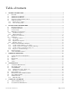
Table of Contents 1. GENERAL INFORMATION....................................................................................................................................4 1.1. FEATURES ............................................................................................................................................................4 1.2. SPECIFICATIONS HFM-200* .................................................................................................................................5 1.3.
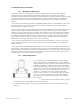
1. General Information The Hastings HFM-200 mass flow meter and HFC-202 flow controller are designed to accurately measure and control mass flow over the range of 10 sccm to 30 slm, without corrections or compensations for gas pressure and temperature with an accuracy of better than ±1% FS. Hastings mass flow instruments do not require any periodic maintenance under normal operating conditions with clean gases. No damage will occur from the use of moderate overpressures (~500 psi/3.45MPa) or overflows.
1.2. Specifications HFM-200* Accuracy1 and Linearity ........................................................................................................................ ±1% F.S. Repeatability ..................................................................................................................................... ±0.05% F.S. Standard Pressure Rating .......................................................................................................................
1.4. Optional 4-20 mA Current Output An option to the standard 0 - 5 VDC output is the 4 - 20 mA current output that is proportional to flow. The 4 - 20 mA signal is produced from the 0 - 5 VDC output of the flow meter. The current loop output is useful for remote applications where pickup noise could substantially affect the stability of the voltage output or long cable runs where cable resistance would cause a voltage signal to decay.
1.5.2. Interconnecting Cables Cables are available from Hastings, in various lengths, to connect from the 15 pin "D" connector on the back of the Power Pod directly to any of the 200 series and 300 series flow instruments (including digital versions). More information about the available cables can be found in the Power Pod 400 bulletin on the Hastings web site. http://www.teledyne-hi.com/pdfs/bulletins.
2. Installation and Operation This section contains the steps necessary to install a new flow meter/controller into operation as quickly and easily as possible. Please read the following thoroughly before attempting to install the instrument. 2.1. Receiving Inspection Carefully unpack the Hastings HFM-200/HFC-202 series instrument and any accessories that have also been ordered. Inspect for any obvious signs of damage to the shipment.
2.4. Mechanical Connections 2.4.1. Standard Configuration The flow meter may be mounted in any position as long as the direction of gas flow through the instrument follows the arrow marked on the bottom of the flow meter case label. The preferred orientation is with the inlet and outlet fittings in a horizontal plane (if operating with a dense gas or at high pressures the instrument must be installed horizontally).
EXAMPLE: Suppose a 4” LFE is selected. The length of 4” diameter tubing or pipe, upstream of the sensor inlet tap, will be a minimum of 20“. The minimum length of 4” tubing or pipe downstream from the sensor outlet tap will be 4”. The length of additional 4” inlet tubing required for the 4” LFE is 20” – 2.5” = 17.5”. The additional length of 4” tubing required for the outlet side of the 4” LFE is 4” – 2.5” = 1.5”. This brings the overall length of the assembly to 19”.
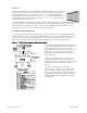
24 Volt Connections Refer to the diagram to the right when connecting 24 Volt units. Connect the positive lead of the power supply to pin 7 of the DE-9 connector and negative lead to pin 4. The supply input is diode protected such that reversing the input polarity will not damage the instrument. The power supply is galvanically isolated from all other pins. General Connection Notes Pin 7 of the DA-15 (15 Volt), Pin 9 of the DE-9 (24 Volt) is the case ground.
2.6.2. Zero Check Turn the power supply on if not already energized. Allow for a 1 hour warm-up. Stop all flow through the instrument and wait 2 minutes. Caution: Do not assume that all metering valves completely shut off the flow. Even a slight leakage will cause an indication on the meter and an apparent zero shift. For the standard 0 - 5 VDC output, adjust the zero potentiometer located on the lower outlet side of the flow meter until the meter indicates zero.
The “COMMAND” pot adjusts the Analog command signal sent to the flow controller. The setting for each controller connected to the power supply can be observed. (Depending on how the power supply was set up, the display could indicate in flow units or percent of full scale).
2.7.3. Operation with an external sensor (Fig. 2.2) In some instances, it might be desirable to use an external sensor to provide process information to the control circuitry in the flow controller. For example, you might want to control the pressure in a vacuum system by adjusting the rate at which the system is backfilled with a gas.
controller circuit establishes control at the new command point. This jumper does not affect the system gain and will not dampen out oscillations. To adjust the response, you need a means of producing a step change in the command voltage from 10% of full scale to 100% of full scale. Follow the steps outlined below: 1) Cover the pins of JP4/JP6 with a jumper. (see fig. 2.2 & fig 2.3) 2) Set the command voltage to 10% of full scale. Allow the flow to stabilize.
3. Theory of Operation This section contains a functional description of Hastings flow controllers. Detailed schematics and parts lists can be obtained by contacting Hastings using the contact information found at the end of this document. In this section and other sections throughout this manual, when a power supply is mentioned, it is assumed that the customer has a Hastings Power Supply. These sections are not applicable if another type of power supply is used. 3.1.
relatively constant over wide ranges of temperature and pressure, the flow meter may be calibrated directly in mass units for those gases. Changes in gas composition usually only require application of a simple multiplier to the air calibration to account for the difference in heat capacity and thus the flow meter is capable of measuring a wide variety of gases. The HFM sensor measures approximately 10 sccm, full scale flow. 3.3.
3.5. Valve The control valve is an “automatic metering solenoid” valve. While most solenoids operate in either the fully open or fully closed state, the automatic metering solenoid valve is designed to control flow (see Figure 3.5). A spring, connected to the plunger assembly, holds a magnetic plunger tightly against an orifice to shut off flow.
4. Maintenance This section contains service and calibration information. Some portions of the instrument are delicate. Use extreme care when servicing the flow controller. 4.1. Authorized Maintenance With proper care in installation and use, the flow controller will require little or no maintenance. If maintenance does become necessary, most of the instrument can be cleaned or repaired in the field. Some procedures may require recalibration. Do not attempt these procedures unless facilities are available.
CAUSE: Plugged orifice. ACTION: Verify the presence of a 10-50 psig pressure across the instrument. If present, shut off gas supply and power supply. Remove orifice per Section 4.9. Examine orifice. If plugged, clean or replace as applicable. Reassemble valve. SYMPTOM: Flow meter reads other than 0.00 VDC with no flow, or there is a small flow when flow meter reads 0.00 VDC. CAUSE: ZERO potentiometer is out of adjustment. ACTION: Shut off all flow. Adjust ZERO potentiometer until output reads 0.00 VDC.
4.3.2. Miscellaneous adjustments Periodically, during normal operation, the ZERO should be checked and adjusted when required. If the instrument is not shutting completely off when the Valve Override CLOSE function is active, or a command of zero flow has been given, then the orifice may require approximately 1/8 turn clockwise. 4.4. End Cap Removal The end cap on the inlet side must be removed to gain access to the filter or shunt assembly. First shut off the supply of gas to the instrument.
B) If Pu >2Pd, use formula 1; otherwise use formula 2. C) Use a consistent set of units for pressure, flow, and density (i.e all lengths, masses, times in the same units, cm, ft, kg, sec etc.) 1 liter/minute = 1.667 x 10⁻⁵ m3/sec, 1 gm/liter = 1 kg/m3, 1 psia = 6895 kg/m*sec2, 1 Pa = 1 kg/m*sec2, D) This formula provides approximate results that tend to be undersized because it neglects pressure drops internal to the flow controller, compressible gas effects and temperature effects.
Lubricate the O-rings slightly with a silicone based grease, and the threads with anti-galling compound. Push the orifice into its hole and screw it in until it is flush with the instrument base. Apply pressure to the inlet side of the instrument. Enable the Valve Override CLOSE function or unplug the instrument. Screw the orifice in a few more turns until the flow through the instrument stops, then turn it an additional 1/4 turn clockwise.
5. Warranty and Repair 5.1. Warranty Repair Policy Hastings Instruments warrants this product for a period of one year from the date of shipment to be free from defects in material and workmanship. This warranty does not apply to defects or failures resulting from unauthorized modification, misuse or mishandling of the product. This warranty does not apply to batteries or other expendable parts, or to damage caused by leaking batteries or any similar occurrence.