
user manual


Communications Setup and Operation Teledyne API - T100 UV Fluorescence SO2 Analyzer
138
A code-activated switch (CAS), can also be used on either port to connect typically
between 2 and 16 send/receive instruments (host computer(s) printers, data loggers,
analyzers, monitors, calibrators, etc.) into one communications hub. Contact Teledyne
API Sales for more information on CAS systems.
To configure the analyzer’s communication ports, use the SETUP>MORE>COMM
menu. Refer to Section 5.7 for initial setup, and to Section 6.2 for additional
configuration inform
ation.
6.4. RS-485 (OPTION)
The COM2 port of the instrument’s rear panel is set up for RS-232 communication but
can be reconfigured for RS-485 communication. Contact Technical Support. If this
option was elected at the time of purchase, the rear panel was preconfigured at the
factory.
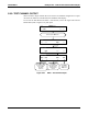
6.5. ETHERNET
When using the Ethernet interface, the analyzer can be connected to any standard
10BaseT or 100BaseT Ethernet network via low-cost network hubs, switches or routers.
The interface operates as a standard TCP/IP device on port 3000. This allows a remote
computer to connect through the network to the analyzer using APICOM, terminal
emulators or other programs.
The Ethernet cable connector on the rear panel has two LEDs indicating the Ethernet’s
current operating status.
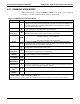
Table 6-2: Ethernet Status Indicators
LED FUNCTION
amber (link) On when connection to the LAN is valid.
green (activity Flickers during any activity on the LAN.
The analyzer is shipped with DHCP enabled by default. This allows the instrument to be
connected to a network or router with a DHCP server. The instrument will automatically
be assigned an IP address by the DHCP server (Section 6.5.2). This configuration is
useful for quickly
getting an instrument up and running on a network. However, for
permanent Ethernet connections, a static IP address should be used. Section 6.5.1 below
details how to configure the instrume
nt with a static IP address.
06807C DCN6650