
user manual


Teledyne API Model T360/T360M Operation Manual Getting Started
41
CONTROL IN
A B C D E F U +
S
P
A
N
Z
E
R
O
CONTROL IN
A B C D E F U +
-
+
5 VDC Power
Supply
S
P
A
N
Z
E
R
O
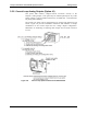
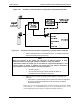
Local Power Connections
External Power Connections
Figure 3-9: Control Inputs Power Connections
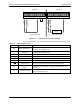
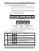
The pin assignments for the digital control inputs can be found in the table below:
Table 3-6: Control Input Pin-outs
INPUT # STATUS DEFINITION ON CONDITION
A
REMOTE ZERO CAL
The Analyzer is placed in Zero Calibration mode. The mode field of
the display will read ZERO CAL R.
B
REMOTE
SPAN CAL
The Analyzer is placed in Span Calibration mode. The mode field of
the display will read SPAN CAL R.
C
SPARE
D
SPARE
E
SPARE
F
SPARE
Digital Ground May be connected to the ground of the data logger/recorder.
U
Pull-up supply for
inputs
Input pin for +5 VDC required to activate pins A – F. This can be from
an external source or from the “+” pin of the instruments STATUS
connector.
+
Internal +5V Supply
Internal source of +5V which can be used to actuate control inputs
when connected to the U pin.
07272B DCN6552