
user manual


Getting Started Teledyne API Model T360/T360M Operation Manual
44
3.6. PNEUMATIC CONNECTIONS
CAUTION!
Do not operate this instrument until you’ve removed dust plugs from SAMPLE
and EXHAUST ports on the rear panel!
3.6.1. Basic Pneumatic Connections
NOTE
In order to prevent dust from getting into the gas flow channels of your analyzer, it was shipped
with small plugs inserted into each of the pneumatic fittings on the back panel. Remove these
plugs before operating the analyzer. It is recommended that they be stored for future use (moving,
storing or shipping the analyzer).
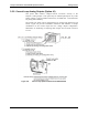
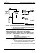
Figure 3-11 illustrates the internal gas flow of the instrument in its basic
configuration. Figure 3-13 illustrates the basic configuration for gas supply and
exhaust lines to the Model T360 Anal
yzer.
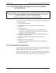
Please refer to Figure 3-4 for pneumatic fittings at the rear panel and Table 3-2
for their descriptions.
NOTE
Sample and calibration gases should only come into contact with PTFE (Teflon), FEP, glass,
stainless steel or brass.
07272B DCN6552