
User's Manual


Advanced FEATURES of the M400E analyzer M400E Ozone Analyzer Operator’s Manual
7.4.3. ANALOG OUTPUT VOLTAGE / CURRENT RANGE SELECTION
In its standard configuration the analog outputs is set to output a 0 – 5 VDC signals. Several other output ranges
are available (see Table 7-9). Each range has is usable from -5% to + 5% of the rated span.
Table 7-9: Analog Output Voltage Range Min/Max
RANGE NAME RANGE SPAN MINIMUM OUTPUT MAXIMUM OUTPUT
0.1V
0-100 mVDC -5 mVDC 105 mVDC
1V
0-1 VDC -0.05 VDC 1.05 VDC
5V
0-5 VDC -0.25 VDC 5.25 VDC
10V
0-10 VDC -0.5 VDC 10.5 VDC
The default offset for all VDC ranges is 0 VDC.
CURR
0-20 mA 0 mA 20 mA
While these are the physical limits of the current loop modules, typical applications use 2-20 or 4-20 mA for the lower and
upper limits. Please specify desired range when ordering this option.
The default offset for all current ranges is 0 mA.
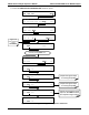
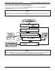
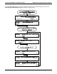
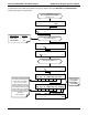
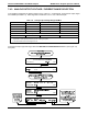
To change the output type and range, select the
ANALOG I/O CONFIGURATION submenu (see Figure 7-4)
then press,
108 04315 Rev. C1