
User's Manual


Theory of Operation M400E Ozone Analyzer Operator’s Manual
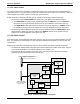
11.3.3.4. Analog Outputs
The analyzer comes equipped with four Analog Outputs: A1, A2, A4 and a fourth that is a spare.
A1 AND A2 OUTPUTS: The first two, A1 and A2 are normally set up to operate in parallel so that the
same data can be sent to two different recording devices. While the names imply that one should be
used for sending data to a chart recorder and the other for interfacing with a data logger, either can be
used for both applications.
Both of these channels output a signal that is proportional to the
O3 concentration of the Sample Gas.
The
A1 and A2 outputs can be slaved together or set up to operated independently. A variety of scaling
factors are available, See Section 6.4.4 for information on setting the range type and scaling factors for
these o
utput channels.
TEST OUTPUT: The third analog output, labeled
A4 is special. It can be set by the user (see Section
7.4.6) to carry the current signal level of any one of the para
meters accessible through the TEST menu of
the unit’s software.
In its standard configuration, the Analyzer comes with all four of these channels set up to output a DC
voltage. However, 4-20mA current loop drivers can be purchased for the first two of these outputs,
A1
and
A2.
OUTPUT LOOP-BACK: All three of the functioning analog outputs are connected back to the A/D
converter through a Loop-back circuit. This permits the voltage outputs to be calibrated by the CPU
without need for any additional tools or fixtures (see Section 7.4.1).
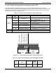
11.3.3.5. External Digital I/O
This External Digital I/O performs two functions.
STATUS OUTPUTS: Logic-Level voltages are output through an optically isolated 8-pin connector
located on the rear panel of the analyzer. These outputs convey good/bad and on/off information about
certain analyzer conditions. They can be used to interface with certain types of programmable devices
CONTROL INPUTS: By connecting these digital inputs to an external source such as a PLC or Data
logger Zero and Span calibrations can be remotely initiated.
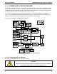
11.3.3.6. I
2
C Data Bus
I
2
C is a two-wire, clocked, digital serial I/O bus that is used widely in commercial and consumer electronic
systems. A transceiver on the Motherboard converts data and control signals from the PC-104 bus to I
2
C. The
data is then fed to the Keyboard/Display Interface and finally onto the relay PCA.
An I
2
C data bus is used to communicate data and commands between the CPU and the Keyboard/Display
Interface, the relay PCA and the power supply for the Photometer UV Lamp. On instruments with IZS Options,
the power supply for the O
3
Generator UV Lamp is also controlled by via the I
2
C bus.
Interface circuits on the Keyboard/Display interface and relay PCA convert the I
2
C data to parallel inputs and
outputs. An additional, interrupt line from the Keyboard to the Motherboard allows the CPU to recognize and
service key presses on the keyboard.
11.3.3.7. Power Up Circuit
This circuit monitors the +5V power supply during start-up and sets the Analog outputs, External Digital I/O
ports, and I
2
C circuitry to specific values until the CPU boots and the instrument software can establish control.
11.3.4. RELAY PCA
200 04315 Rev. C1