
User's Manual


Theory of Operation M400E Ozone Analyzer Operator’s Manual
11.3.4.3. Valve Control
The valve that switches the gas stream to and from the analyzer’s O
3
scrubber during the measure/reference
cycle (see Section 11.1.3) is operated by an electronic switch located on the relay
PCA. This switch, under CPU
control, supplies the +12VDC needed to activate each valve’s solenoid.
Similar valves also controlled by the relay PCA are included in the following optional components:
On instruments with the
ZERO/SPAN valve option (OPT- 50A) there are two additional valves:
The
ZERO/SPAN valve selects which calibration gas inlet (the ZERO gas inlet or the SPAN Gas
Inlet) is the source of gas when the analyzer is in one of its calibration modes (see Figure 5-3).
The
SAMPLE/CAL valve selects either the sample inlet when the analyzer is in SAMPLE mode or
the calibration gas stream when the analyzer is in one of its calibration modes (see Figure 5-3).
On instruments with the
IZS valve option (OPT- 51A) one additional valves (the SAMPLE/CAL valve)
selects either the sample inlet when the analyzer is in
SAMPLE mode or the dry air inlet when the
analyzer is in one of its calibration modes (see Figure 3-6).
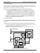
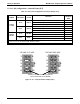
11.3.4.4. Heater Control
In the base version of the Model 400E photometric analyzer, there is only one DC heater operated by the relay
PCA. It is attached to the Photometer UV Lamp housing and maintains the temperature of the UV Lamp at a
constant 58ºC.
Additional DC heater also controlled by the relay PCA, are included in the following optional components:
On instruments with Zero/Span valve option (OPT-50A) the metal wool scrubber option (OPT- 68) there
is a DC heater embedded in the scrubber maintains it at a constant 110ºC.
On instruments with the IZS valve option (OPT- 51A) there is a DC heater attached to the IZS O
3
generator UV Lamp that maintains it at a constant 48ºC
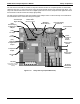
Thermistor(s) – Photometer Lamp
Temperature and Optional IZS O
3
Generator Lamp Temperature)
RELAY PCA
DC
Control
Logic
Preamplifiers
and Signal
Conditioning
MOTHER BOARD
A/D
Converter
(V/F)
CPU
Themocouple(s)
(used on Optional Metal
Wool Scrubber)
DC HEATERS
(UV LAMP Heaters)
THERMOCOUPLE
CONFIGURATION
JUMPER
(JP5)
Cold Junction
Compensation
Solid State
AC Relays
AC HEATER
(optional
Metal Wool Scrubber)
Figure 11-10: Heater Control Loop Block Diagram.
204 04315 Rev. C1