
User's Manual


M400E Ozone Analyzer Operator’s Manual Maintenance Schedule & Procedures
12.3.4. PERFORMING LEAK CHECKS
Leaks are the most common cause of analyzer malfunction; Section 12.3.4.1 presents a simple leak check
procedure. Section 12.3.4.2 details a more thorough procedure.
12.3.4.1. Vacuum Leak Check and Pump Check
This method is easy and fast. It detects, but does not locate most leaks; it also verifies that the sample pump is
in good condition.
1. Turn the analyzer ON, and allow enough time for flows to stabilize.
2. Cap the sample inlet port.
3. After 2 minutes, when the pressures have stabilized, note the SAMP FL and PRES test function
readings on the front panel.
4. If SAMP FL < 10 CC/M then the analyzer is free of any large leaks.
5. If PRES < 10 IN-HG-A then the sample pump diaphragm is in good condition.
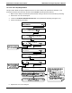
12.3.4.2. Pressure Leak Check
If you cannot locate the leak by the above procedure, obtain a leak checker similar to the T-API part number
01960, which contains a small pump, shut-off valve and pressure gauge. Alternatively, a tank of pressurized
gas, with the two-stage regulator adjusted to ≤ 15 psi; a shutoff valve and pressure gauge may be used.
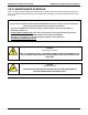
CAUTION
General Safety Hazard
Once the fittings have been wetted with soap solution, DO NOT apply / re-apply
vacuum, as this will cause soap solution to be drawn into the instrument,
contaminating it.
DO NOT exceed 15 psi pressure.
1. Turn OFF power to the instrument.
2. Install a leak checker or tank of gas as described above on the sample inlet at the rear panel.
3. Install a cap on the exhaust fitting on the rear panel.
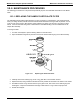
4. Remove the instrument cover and locate the sample pump. Disconnect the two fittings on the sample
pump and install a union fitting in place of the pump. The analyzer cannot be leak checked with the
pump in line due to internal leakage that normally occurs in the pump.
5. Pressurize the instrument with the leak checker, allowing enough time to pressurize the instrument
through the critical flow orifice fully. Check each fitting with soap bubble solution, looking for bubbles.
Once the fittings have been wetted with soap solution, do not re-apply vacuum, as it will draw soap
solution into the instrument and contaminate it. Do not exceed 15 psi pressure.
6. If the instrument has one of the zero and span valve options, the normally closed ports on each valve
should also be separately checked. Connect the leak checker to the normally closed ports and check
with soap bubble solution.
7. If the analyzer is equipped with an IZS option, connect the leak checker to the dry air inlet and check
with soap bubble solution.
8. Once the leak has been located and repaired, the leak-down rate should be < 1 in-Hg (0.4 psi) in 5
minutes after the pressure is shut off.
04315 Rev. C1 225