
User's Manual


Getting Started M400E Ozone Analyzer Operator’s Manual
3.2.1.1. Ventilation Clearance
Whether the analyzer is set up on a bench or installed into an instrument rack, be sure to leave sufficient
ventilation clearance.
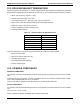
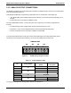
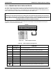
Table 3-3: Ventilation Clearance
AREA MINIMUM REQUIRED CLEARANCE
Back of the instrument
4 in.
Sides of the instrument
1 in.
Above and below the instrument
1 in.
Various rack mount kits are available for this analyzer. See Section 5.1 of this manual for more information.
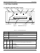
3.3. ELECTRICAL CONNECTIONS
3.3.1. POWER CONNECTION
Attach the power cord to the analyzer and plug it into a power outlet capable of carrying at least 10 A current at
your AC voltage and that it is equipped with a functioning earth ground.
CAUTION
Electrical Shock Hazard
HIGH VOLTAGES ARE PRESENT INSIDE THE ANALYZERS CASE
POWER CONNECTION MUST HAVE FUNCTIONING GROUND CONNECTION.
DO NOT DEFEAT THE GROUND WIRE ON POWER PLUG.
TURN OFF ANALYZER POWER BEFORE DISCONNECTING OR
CONNECTING ELECTRICAL SUBASSEMBLIES.
DO NOT OPERATE WITH COVER OFF.
CAUTION
General Safety Hazard
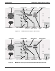
THE M400E ANALYZER CAN BE CONFIGURED FOR BOTH 100-130 V AND
210-240 V AT EITHER 50 OR 60 HZ.
TO AVOID DAMAGE TO YOUR ANALYZER, MAKE SURE THAT THE AC POWER
VOLTAGE MATCHES THE VOLTAGE INDICATED ON THE ANALYZER’S SERIAL
NUMBER LABEL TAG (SEE FIGURE 3-2) BEFORE PLUGGING THE M400E INTO
LINE POWER.
16 04315 Rev. C1