
User's Manual


Getting Started M400E Ozone Analyzer Operator’s Manual
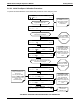
3.6. INITIAL CALIBRATION OF THE M400E ANALYZER
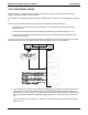
To perform the following calibration you must have sources for zero air and calibration (span) gas available for
input into the inlet/outlet fittings on the back of the analyzer (see Section 3.4).
The metho
d for performing an initial calibration for the Model 400E photometric ozone analyzer differs slightly
depending on the whether or not any of the available internal zero air or valve options are installed.
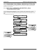
See Section 3.6.2 for instructions for initial calibration of the M400
E analyzers in their base configuration.
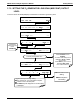
See Section 3.7.4 for instructions for initial calibration of M400E analyzers possessing IZS Valve Options
(OPT-
51A).
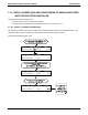
See Section 9.3 for information regarding setup and calibration of M400E analyzers with Z/S Valve
option
s (OPT-50A).
If you are using the M400E analyzer for EPA monitoring, only the calibration method described in Chapter
10 should be used.
3.6.1. INTERFERENTS FOR O
3
MEASUREMENT
The detection of O
3
is subject to interference from a number of sources including, SO
2
, NO
2
, NO, H
2
O AND
aromatic hydrocarbon meta-xylene and mercury vapor. The Model 400E successfully rejects interference from
all of these with the exception of mercury vapor.
If the Model 400E is installed in an environment where the presence of mercury vapor is suspected, steps should
be taken to remove the mercury vapor from the sample gas before it enters the analyzer.
For more detailed information regarding O
3
measurement interferences, see Section 11.1.4
NOTE
The presence of mercury vapor is highly unlikely in the types of applications for which M400E analyzers
with IZS options installed are normally used.
30 04315 Rev. C1