
User's Manual


M400E Ozone Analyzer Operator’s Manual Basic Operation of the M400E Analyzer
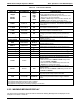
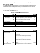
Table 6-2: Test Functions Defined
DISPLAY PARAMETER UNITS DESCRIPTION
RANGE
- -
RANGE1
RANGE2
RANGE
PPB,
PPM,
UGM
&
MGM
The Full Scale limit at which the reporting range of the
analyzer’s ANALOG OUTPUTS is currently set.
THIS IS NOT the Physical Range of the instrument. See
Section 6.4.4.1 for more information.
If DUAL or AUTO Range modes have been selected, two
RANGE functions will appear, one for each range.
STABIL
STABILITY
MV
Standard deviation of O
3
Concentration readings. Data points
are recorded every ten seconds. The calculation uses the last
25 data points.
O
3
MEAS
PHOTOMEAS
MV
The average UV Detector output during the MEASURE portion
of the analyzer’s measurement cycle.
O
3
REF
PHOTOREF
MV
The average UV Detector output during the REFERENCE
portion of the analyzer’s measurement cycle.
O
3
GEN
2
O3GENREF
MV
The current output of the O
3
generator reference detector
representing the relative intensity of the O
3
generator UV
Lamp.
(2)
O
3
DRIVE
1
O3GENDRIVE
MV
The Drive voltage used to control the intensity of the O
3
generator UV Lamp.
(1)
PHOTO POWER
PHOTOPOWER
MV
Photometer lamp drive output.
PRES
SAMPPRESS
IN-HG-A
The absolute pressure of the Sample Gas as measured by a
solid-state pressure sensor.
SAMP FL
SAMPFLOW
CC/MIN
Sample Gas mass flow rate as measured by the Flow Sensor
located between the Optical Bench and the Sample Pump.
SAMPLE TEMP
SAMPTEMP
C
The Temperature of the gas inside the Sample Chamber.
PHOTO LAMP
PHOTOLTEMP
C
The Temperature of the UV Lamp in the Optical Bench.
O
3
SCRUB
3
O3SCRUBTEMP
C
The current temperature of the Metal Wool Scrubber.
(3)
O
3
GEN TMP
1
O3GENTEMP
C
The Temperature of the UV Lamp in the O
3
Generator.
(1)
BOX TEMP
BOXTEMP
C
The temperature inside the analyzer chassis.
SLOPE
SLOPE
- -
The Slope of the instrument as calculated during the last
calibration activity.
When the unit is set for SINGLE or DUAL Range mode,
this is the SLOPE of RANGE1.
When the unit is set for AUTO Range mode, this is the
SLOPE of the currently active range.
OFFSET
OFFSET
PPB
The Offset of the instrument as calculated during the last
calibration activity.
When the unit is set for SINGLE or DUAL Range mode, this is
the OFFSET of RANGE1.
TEST
4
TESTCHAN
MV
Displays the signal level of whatever Test function is currently
being output by the Analog Output Channel A4.
(4)
TIME
CLOCKTIME
HH:MM:SS
The current time. This is used to create a time stamp on iDAS
readings, and by the AutoCal feature to trigger calibration
events.
1
Only appears if IZS option is installed.
2
Only appears if IZS Reference Sensor option is installed.
3
Only appears if Metal Wool Scrubber option is installed.
4
Only appears if Analog Output A4 is actively reporting a Test Function.
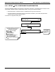
6.2.2. WARNING MESSAGE DISPLAY
The most common and serious instrument failures will activate Warning Messages that are displayed on the
analyzer’s Front Panel. These are:
04315 Rev. C1 61