
User's Manual

Teledyne API M100E Analyzer Operation Manual Theory Of Operation
245
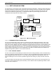
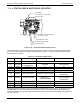
11.4.9.3. THERMISTOR INTERFACE
This circuit provides excitation, termination and signal selection for several negative-coefficient, thermistor
temperature sensors located inside the analyzer. They are as follows:
SAMPLE CHAMBER TEMPERATURE SENSOR: The source of this signal is a thermistor imbedded in the of
the sample chamber block. It measures the temperature of the sample gas in the chamber. This data are used
by the CPU to control sample chamber the heating circuit and as part of the SO
2
, calculations when the
instrument’s Temperature/Pressure Compensation feature is enabled.
This measurement is stored in the analyzer. Memory as the Test Function RCEL TEMP and is viewable as a test
function (refer to Section 6.2.1) through the analyzer’s front panel.
IZS OPTION PERMEATION TU
BE TEMPERATURE SENSOR: This thermistor, attached to the permeation tube
in the IZS option, reports the current temperature of that tube to the CPU as part of control loop that keeps the
tube at a constant temperature.
BOX TEMPERATURE SENSOR: A thermistor is attached to the motherboard. It measures the analyzers inside
temperature. This information is stored by the CPU and can be viewed by the user for troubleshooting purposes
through the front panel display. This measurement is stored in the analyzer. Memory as the test function BOX
TEMP and is viewable as a test function (refer to Section 6.2.1) through the analyzer’s front panel.
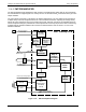
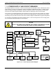
11.4.10. ANALOG OUTPUTS
The analyzer comes equipped with four Analog Outputs: A1, A2, A3 and a fourth that is a spare.
A1 and A2 Outputs:
The first two, A1 and A2 are normally set up to operate in parallel so that the same data
can be sent to two different recording devices. While the names imply that one should be used for sending data
to a chart recorder and the other for interfacing with a data logger, either can be used for both applications.
Both of these channels output a signal that is proportional to the SO
2
concentration of the sample gas. The A1
and A2 outputs can be slaved together or set up to operated independently. A variety of scaling factors are
available, refer to Section 6.7 for information on setting the range type and Section 6.9.4 for adjusting the
electroni
c sca
ling factors of these output channels
Test Output
: The third analog output, labeled A3 is special. It can be set by the user (refer to Section 6.9.10) to
carry the signal level of any one of the parameters accessible through the TEST menu of the unit’s software.
In its standard configuration, the Analyzer comes with all four of these channels set up to output a DC voltage.
However, 4-20mA current loop drivers can be purchased for the first two of these outputs (A1 and A2 - refer to
Section 5.4).
Outpu
t
Loop-back
: All three of the functioning analog outputs are connected back to the A/D converter through
a Loop-back circuit. This permits the voltage outputs to be calibrated by the CPU without need for any additional
tools or fixtures (refer to Section 6.9.4.2).
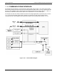
11.4.11. EXTERNAL DIGITAL I/O
This External Digital I/O performs two functions.
STATUS OUTPUT
S: Logic-Level voltages are output through an optically isolated 8-pin connector located on
the rear panel of the analyzer. These outputs convey good/bad and on/off information about certain analyzer
conditions. They can be used to interface with certain types of programmable devices (refer to Section 7.3.1.1).
CO
NTR
OL INPUTS
: By applying +5VDC power supplied from an external source such as a PLC or Data logger
(refer to Section 7.3.1.2), Zero and Span calibrations can be initiated by conta
ct closures on the rear panel.
04515F DCN6048