
User's Manual


Troubleshooting & Repair Teledyne API M100E Analyzer Operation Manual
276
12.6.11. PMT PREAMPLIFIER BOARD
To check the correct operation of the preamplifier board, we suggest the technician carry out the electrical and
optical tests described in 6.9.5 and 6.9.6.
If the ETEST
fails, the preamplifier board may be faulty.
12.6.12. PMT TEMPERATURE CONTROL PCA
The TEC control printed circuit assembly is located on the sensor housing assembly, under the slanted shroud,
next to the cooling fins and directly above the cooling fan.
If the red LED located on the top edge of this assembly is not glowing the control circuit is not receiving
power.
Check the analyzers power supply, the Relay board’s power distribution circuitry and the wiring connecting
them to the PMT temperature control PCA.
12.6.12.1. TEC CONTROL TEST POINTS
Four test points are also located at the top of this assembly they are numbered left to right start with the T1 point
immediately to the right of the power status LED. These test points provide information regarding the functioning
of the control circuit.
To determine the current running through the control circuit, measure the voltage between T1 and T2.
Multiply that voltage by 10.
To determine the drive voltage being supplied by the control circuit to the TEC, measure the voltage
between T2 and T3.
If this voltage is zero, the TEC circuitry is most likely open.
If the voltage between T2 and T3 = 0 VDC and the voltage measured between T1 and T2 = 0 VDC
there is most likely an open circuit or failed op amp on control PCA itself
If the voltage between T2 and T3 = 0 VDC and the voltage measured between T1 to T2 is some
voltage other than 0 VDC, the TEC is most likely shorted
T4 is tied directly to ground. To determine the absolute voltage on any one of the other test points make a
measurement between that test point and T4.
12.6.13. HIGH VOLTAGE POWER SUPPLY
The HVPS is located in the interior of the sensor module and is plugged into the PMT tube (refer to Figure
11-14). It requires 2 voltage inputs. The first is +15 which powers the supply. The second is the programming
voltage which is generated on the Preamp Board. This power supply is unlike a traditional PMT HVPS. It is like
having 10 independent power supplies, one to each pin of the PMT. The test procedure below allows you to test
each supply.
1. Check the HVPS test function via the front panel Turn off the instrument and record the reading level.
Adjustment of the HVPS output level is covered in the hardware calibration procedure in Section 12.7.2.8.
2.
Turn off the instru
ment.
3. Remove the cover and disconnect the 2 connectors at the front of the PMT housing.
4. Remove the end plate from the PMT housing.
5. Remove the HVPS/PMT assembly from the cold block inside the sensor. Un-plug the PMT.
6. Re-connect the 7 pin connector to the Sensor end cap, and power-up the instrument.
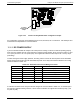
7. Check the voltages between the pairs of pins listed in Table 12-9. The result for each pair should be equal
and ap
proxim
ately 10% of the reading level recorded in Step 1.
04515F DCN6048