
User's Manual


Troubleshooting & Repair Teledyne API M100E Analyzer Operation Manual
292
12.7.2.8. PMT HARDWARE CALIBRATION (FACTORY CAL)
The sensor module hardware calibration adjusts the slope of the PMT output when the instrument’s slope and
offset values are outside of the acceptable range and all other more obvious causes for this problem have been
eliminated.
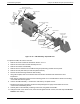
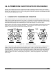
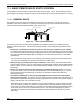
Figure 12-16: Pre-Amplifier Board Layout
25. Set the instrument reporting range type to SNGL (refer to Section 6.7.4).
26.
Perform a
zero–point calibration using zero air (refer to Chapter 8).
27. Let the instru
ment stabilize by allowing it to run for one hour.
28. Adjust the UV Lamp (refer to Section 12.7.2.5).
29. Perform a L
AMP CALIBRATION procedure (refer to Section 6.9.7).
30. Locate the Preamp bo
ard (refer to Figure 3-9).
31. Locate the Fo
llowing Components On the Preamp board (refer to Figure 12-16):
HVPS coarse adjustment switch (Range
0-9, then A-F).
HVPS fine adjustment switch (Range 0-9, then A-F).
Gain adjustment potentiometer (Full scale is 10 to 12 turns).
32. Set the HVPS coarse adjustment to its minimum setting (0).
33. Set the HVPS fine adjustment switch to its maximum setting (F).
34. Turn the gain adjustment potentiometer clockwise to its maximum setting.
35. Set the front panel display to show STABIL (refer to Section 6.2.1).
36.
Feed span g
as into the analyzer.
37. Wait until the STABIL value is below 0.5 ppb.
NOTE
Use a span gas equal to 80% of the reporting range.
Example: for a reporting range of 500 ppb, use a span gas of 400 ppb.
04515F DCN6048