Portable Oxygen Monitor OPERATING & SERVICE INSTRUCTIONS FOR MX300-I PORTABLE OXYGEN MONITOR P/N M75707 REV 1 ECO # 04-0088 0086 TYPE B EQUIPMENT: Equipment providing a particular degree of protection against electric shock, particularly regarding— • Allowable LEAKAGE CURRENT • Reliability of the protective earth connection (if present).
MX300-I Copyright © 2002 Teledyne Analytical Instruments All Rights Reserved No part of this manual may be reproduced, transmitted, transcribed, stored in a retrieval system, or translated into any other language or computer language in whole or in part, in any form or by any means, whether it be electronic, mechanical, optical, manual, or otherwise, without prior written consent of Teledyne Instruments, Analytical Instruments, 16830 Chestnut Street, City of Industry, CA 91749-1580 FCC Statement This equi
Portable Oxygen Monitor About This Manual The MX300-I Operator's Manual provides both introductory and detailed information for configuring and operating these instruments. The manual takes you from the time you unpack the instrument until you complete the first gas analysis. The bulk of the manual contains operating procedures and information. There are also cautions, warnings, and guidelines to ensure that your monitor operates normally and to its full potential.
MX300-I Safety Messages Your safety and the safety of others are very important. Please carefully read the following safety messages. Safety message are indented to alert the user of potential hazards. Each safety message is associated with a safety alert symbol. These symbols are found in the manual and on the instrument. The definition of these symbols is described below: CAUTION: Refer to the instructions for details on the specific danger.
Portable Oxygen Monitor Table of Contents Safety Messages .......................................................................... iv List of Figures................................................................................ v List of Figures.............................................................................. vii List of Tables .............................................................................. viii Introduction ...................................................................
MX300-I 2.3.1 Humidity 26 2.3.2 Temperature 27 2.3.3 Pressure 27 2.3.4 Discrepancy in Readings 28 2.3.5 Anesthetic Gases 28 2.3.5.1 Gases That Induce Reading Error 28 2.3.5.2 Care After Use in Nitrous Oxide 29 2.3.6 Cleaning 2.4 Do’s and Don’ts 30 30 Service Manual ............................................................................ 33 3.1 General Service Information 33 3.2 Overall Maintenance 33 3.3 Battery Maintenance 33 3.4 Sensor Maintenance 34 3.5 Calibration 34 3.
Portable Oxygen Monitor List of Figures Figure 1-1: MX300-I Front View ...................................................... 9 Figure 2-1: Installing the R17MED Sensor .................................... 16 Figure 2-2: Sensor Cable Connection to Monitor ......................... 17 Figure 2-3: Mounting the Sensor in the Tee Adapter..................... 17 Figure 2-4: V-Mount Adapter Installation ....................................... 18 Figure 2-5: Brass Insert for Universal Mounting Clamp .............
MX300-I List of Tables Table 2-1: Oxygen Reading Error in a Mixture of Anesthetic Gas. 29 Table 3-1 Troubleshooting ............................................................ 37 Table 3-2 Error Codes...................................................................
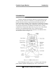
Portable Oxygen Monitor Introduction Introduction Teledyne Analytical Instruments MX300-I Oxygen Monitor with alarms here after referred to as MX300-I is a portable instrument that provides fast and accurate oxygen monitoring and incorporates an audio/visual alarm capability. These instruments are designed to monitor up to 100% oxygen concentration in medical gas mixtures. Because they are microprocessor-based, the MX300-I instruments have a unique combination of features that make them very easy to use.
Introduction MX300-I Options for alternate display configuration). An integral battery life indicator is displayed “on demand” with the MX300-I. The instrument is powered by three AA alkaline batteries and is designed to operate for 2000 hours in non-alarm state. Oxygen analysis is linear across the single range of 0-100% using Teledyne’s class R17MED oxygen sensor. A unique sensor failure alarm is incorporated which warns the user if the sensor signal is lost or low.
Portable Oxygen Monitor Introduction 1.2 Features The MX300-I is a compact, versatile instrument capable of rapidly measuring the oxygen content of an atmosphere or environment accurately to ±2% over the range 0-100% oxygen.
Introduction MX300-I Section 2.1.5. In addition to the above instrument configuration options, the following optional equipment is available for your instrument: • Universal Pole Mounting Clamp (P/N CP 2343) • V-Mount Pole Clamp (P/N CP 2344) • V-Mount Wall Adapter P/N B 647) • 0-1 VDC Interface Cable (P/NB-75554) • RS 232 Interface Cable (P/N B-75555) 1.
Portable Oxygen Monitor Introduction is illuminated on the LCD and the audible and visual alarms are activated whenever a fault is detected. 1.5.1 Sensor The MX300-I uses the Teledyne Class R17MED disposable oxygen sensor. The sensor is made up of a sensing cathode and anode (fuel) immersed in electrolyte and packaged in a small plastic container.
Introduction MX300-I The oxygen level is calculated and then displayed on the liquid crystal display (LCD) on the front panel. In the MX300-I monitor, user-programmed high and low alarm set points are stored in random access memory (RAM), which resides within the microprocessor. The oxygen level calculated by the microprocessor is compared to these set points, and an alarm activated, if necessary. The audio alarm is used for both the concentration alarms and the sensor disconnects alarm.
Portable Oxygen Monitor Operation Operation Note: Upon receipt, INSPECT THE ENTIRE UNIT FOR DAMAGE. Check the unit and all included accessories for broken or loose parts. If damaged, DO NOT USE. Notify the shipper, and consult Teledyne Analytical Instruments. Note: This equipment is internally powered using 3 AA batteries. CAUTION: THE MX300-I, OXYGEN SENSOR AND ASSOCIATED HARDWARE ARE NON-STERILE DEVICES. DO NOT AUTOCLAVE THE INSTRUMENT OR SENSOR, AS THIS WILL DAMAGE THE EQUIPMENT. 2.
Operation MX300-I 2.1.1 Sensor Installation or Replacement Note: The R17MED oxygen sensor must be installed before the oxygen analyzer/monitor can be operated 1. Remove the new sensor from its protective bag. Inspect the sensor for damage or electrolyte leakage. If the sensor is damaged, obtain a replacement. Do not use the defective sensor as it may damage the unit. WARNING: THE SENSOR ELECTROLYTE IS CAUSTIC. DO NOT LET IT COME IN CONTACT WITH SKIN. IF IT DOES, FLUSH AFFECTED AREA WITH WATER.
Portable Oxygen Monitor Operation Figure 2-2: Sensor Cable Connection to Monitor Note: When the MX300-I instrument is used for diffusion sampling (i.e., incubators, tents, etc.), the plastic flow diverter must be removed from the R17MED sensor. If the sensor is used in breathing circuits, etc, the diverter must be used as shown in Figure 2-3.
Operation MX300-I 2.1.2 Mounting The MX300-I can be mounted in several ways depending on the optional equipment ordered at the time of purchase. See Section 1.3. 2.1.2.1 V-MOUNT ADAPTER INSTALLATION The V-Mount Adapter consists of a matching plastic plate with integral V-grooves that attach to the rear of the instrument. To install V-Mount Adapter remove battery compartment door by prying up the hinged latch at the bottom of the cover, then slide the adapter plate into grooves provided in rear case.
Portable Oxygen Monitor Operation 2.1.3 Battery Installation Note: Three “AA” alkaline batteries must be installed in the unit before the monitor will operate. The unit must be recalibrated whenever new batteries are installed and the HI and LOW alarm set points must be reset to the desired values To install the batteries: 1. Turn the unit off (if it is on). 2. Hold the instrument face down in the palm of your hand. Use a coin to pry up the latch that secures the battery compartment door.
Operation MX300-I 4. Re-install the battery compartment door. When the unit is first turned on the display will momentarily display all LCD segments. During this period diagnostic tests are being conducted to insure the circuits are functioning correctly. The unit will activate the audible and visual alarms for about 1 second. The LCD will flash continuously indicating the unit is in the unlocked position ready for calibration.
Portable Oxygen Monitor Operation made to the settings. If the batteries have just been installed the LCD will flash 00.0 4. As with most oxygen analyzer(s) the highest level of accuracy is achieved when calibration is conducted using 100% oxygen. After installing the flow diverter as noted in Section 2.1.1, insert the sensor into the plastic tee and connect to a supply of pure dry oxygen flowing at 1-2 liters per minute.
Operation MX300-I should never be used where a high degree of accuracy is needed. Note: Never calibrate the unit in humidified gas, as water vapor makes the oxygen concentration appear lower than it really is. See Appendix: Humidity. CAUTION: DO NOT ADJUST THE CALIBRATION SETTINGS IN AIR AFTER THE 100% CALIBRATION, AS THIS WILL CANCEL THE MORE ACCURATE 100% CALIBRATION. THE 100% CALIBRATION MAY BE REPEATED AS MANY TIMES AS DESIRED. 8.
Portable Oxygen Monitor Operation designed to prevent crossing of HI/LO alarm settings. If you attempt to set the LO alarm higher than the HI alarm, it will push the HI alarm setting up as you continue to rise the LO alarm set point. This also applies when attempting to set the HI alarm lower than the LO alarm. 3. To test the alarms, unlock the controls by pressing the LOCK/UNLOCK key and then press ALARM TEST key.
Operation MX300-I Figure 2-9: 0-1 VDC or RS 232 Digital Output Port If your instrument is set for analog (0-1 VDC) output, you can reconfigure it to use the digital output by changing a jumper on the internal PC board. To activate the digital output: 1. Remove the batteries and remove the five screws that hold the case together. 2. Remove the rear case section leaving the PCB in the front half of the case. 3. Remove jumper at position JP3 and reinstall it at position JP7. 4.
Portable Oxygen Monitor Operation 2.2 Use 2.2.1 Procedure Note: Prior to use, always test the batteries and alarms (if applicable). Also check calibration, the sensor for leaks and damage, and the alarm settings. The AX/MX300-I instruments can be used to measure a gas mixture for oxygen in two basic modes: • In the inhalation side of breathing circuit ahead of antibacterial filters, humidifiers and medicating devices. • In confined volumes such as incubators or tents.
Operation MX300-I R17MED sensor so that it does not interfere with the rapid exchange of gases to and from the sensing surface of the sensor. CAUTION: FAILURE TO REMOVE THE DIVERTER IN THESE APPLICATION AREAS WILL RESULT IN A MARKED LOWERING OF THE RESPONSE TIME OF THE SENSOR. The R17MED sensor can be placed or hung inside incubators, tents, etc.
Portable Oxygen Monitor Operation 2.3.2 Temperature The R17MED oxygen sensor adjusts for ambient temperature changes in the range of 0–40°C (32–106°F). Since the thermistor that compensates for these changes is located in the rear of the sensor assembly, it is important that gas mixtures, flowing over the front of the sensor, be at room temperature. Reading errors may occur if hot gases from a heated humidifier are directed past a sensor teed into a breathing circuit.
Operation MX300-I 2.3.4 Discrepancy in Readings The MX300-I instrument should be used to measure the oxygen concentration exiting another oxygen mixing device or life support system (i.e., a blender, incubator or anesthesia machine). The information obtained from the MX300-I should never be used to adjust a life-support system, but should only be used as an indication that the life support system or device may require service and/or calibration.
Portable Oxygen Monitor Operation Table 2-1: Oxygen Reading Error in a Mixture of Anesthetic Gas Gas or Vapor Level (Balance: Mixture of 30% O2 / 70% N2O, except where noted) Gas or Vapor Test Level Oxygen Reading Error Helium 50%, balance O2 0% Nitrous Oxide 80%, balance O2 0% Carbon Dioxide 10%, balance O2 0% Halothane 4% < 1.5% O2 * Enflurane 5% < 1.5% O2 * Isoflurane 5% < 1.5% O2 * Sevoflurane 5% < 1.5% O2 * Desflurane 15% < 1.
Operation MX300-I After exposure to nitrous oxide mixtures, the sensor should be left in 100% oxygen overnight (e.g., left in a breathing circuit that has been flushed with pure oxygen). If this is not practical, when using the Tee, remove the plastic flow diverter and leave the sensor in room air. If the oxygen reading continues to drop after each use in nitrous oxide the sensor should be removed from service.
Portable Oxygen Monitor Operation • Test batteries regularly and replace when battery indicator shows low battery (no bars remaining) • Make sure keys are locked by using the LOCK/UNLOCK key feature. • Keep the unit, sensor and connections dry, or on the dry side of the breathing circuit. • Recalibrate after replacing the batteries. • Recalibrate after replacing the sensor. • Use properly installed alkaline batteries only. • Make sure the R17MED sensor is properly attached.
Operation MX300-I • Use cleaning agents or liquids in the cable receptacles or around the battery compartment. • Place the unit itself in a water vapor-saturated environment. • Expose the LCD to excessive sunlight. • Expose the unit to a condensing water environment such as a mist tent.
Portable Oxygen Monitor Service Manual Service Manual 3.1 General Service Information The Teledyne Model MX300-I Portable Oxygen Monitor is designed to be robust yet compact in size. In order to achieve maximum reliability in a microprocessor-based instrument, a single PC board is used which relies exclusively on surface mount technology. Without access to specialized probes and test equipment, troubleshooting and repair of circuit board components are not feasible.
Service Manual MX300-I DO: Recalibrate after replacing batteries. The MX300-I instrument incorporates a battery test feature that provides the approximate amount of useful life remaining on the set of batteries. Excessive alarm activation will wear down the battery faster than usual. The minimum detectable change in battery voltage corresponds to an increment of about 50 hours, meaning that the battery voltage reading may not change for several hours at a time.
Portable Oxygen Monitor Service Manual functional at this point. After calibration is completed, the alarm set points will need to be reset. To calibrate the instrument refer back to Section 2.1.3. 3.6 Alarms To set the alarms on the MX300-I monitor, refer to Section 2.1.4. 3.7 Gas Sampling 3.7.1 Humidity Humidity does not directly affect the accuracy of the sensor's measurement.
Service Manual MX300-I during this period since this error will be eliminated when both the thermistor and sensing electrode have had sufficient time to come to thermal equilibrium. This can take up to 2 hours. 3.7.3 Pressure Virtually all gas sensors and monitors measure the partial pressure, not the percentage, of the gas that they sense. The only time that these instruments can accurately read percentages is when the total pressure does not vary over time between calibrations and use.
Portable Oxygen Monitor Service Manual investigation should be made until the discrepancy in readings is resolved. The troubleshooting section of this manual may provide additional assistance in locating the problem. Note: The MSDS on this material is located in the Appendix. It is also available upon request through the Teledyne Environmental, Health and Safety Coordinator. Contact at (626) 934-1592 3.
Service Manual MX300-I Symptom Why What To Do the reading again. E) Try calibrating with a known good sensor; if this fails, see symptom "Reading drifts over 2–3%..." The sensor does not react to changes in oxygen concentration, or the readings are unstable and drifting. Water is condensing on the sensing surface. Electrical interference is disrupting the electronics A) Remove the sensor from tee adapter and unscrew the plastic flow diverter.
Portable Oxygen Monitor Symptom Service Manual Why What To Do ventilate the patient, water vapor actually dilutes the gas. See Appendix: Humidity, Temperature. D) If a blender is used, check its calibration. See Appendix: Discrepancy in Readings. The unit has stopped working and the LCD is displaying alphanumeric figures.
Service Manual MX300-I Symptom Cannot adjust calibration or alarm settings Why What To Do Critical settings require two keys be pressed in a specific order. A) If display is not flashing press lock key once to activate keys. Press desired function followed by the Up and Down key. LOCK/UNLOCK key is active Note: In the event that none of these procedures produce desired results, remove the batteries and return the unit to Teledyne for repair. 3.
Portable Oxygen Monitor Service Manual 50 5 The ADC circuit failed during POST. 6 (5) 6 A stuck key has been detected.
Service Manual MX300-I non-abrasive cleaner solution to periodically clean the keypad and screen. An aerosol jet spray of the type commonly used to clean computer keyboards can be used to dislodge dirt and accumulations from the keypad. The Error Code Table (Table 3-2) includes a description of certain fault codes which are diagnostic of some common (usually electronic) problem with the instrument. Some of these codes refer to specific components on the PCB that are problematic or have failed.
Portable Oxygen Monitor Appendix Appendix A.1 Specifications Range: 0-100% oxygen Accuracy: +2% of full scale (at constant temperature and pressure) Response Time: 90% in less than 8 seconds at 25 °C Battery Life: Approximately 2000 hr. continuous use in a non-alarm condition System Power: 3 AA alkaline batteries. Sensor Type: Class R17MED Expected Life: 36 months in air. (10 months when continuously exposed to 100% oxygen) Dimensions: 2.5" W × 1.25" D × 4.5" H (66 mm x 33mm × 111.
Appendix MX300-I A.2 Spare Parts List QTY 1 PART NO C43690-R17MED 3 1 1 1 1 1 1 1 1 B99 B69934 A268 B-74543 D-74459 C-74461 B-74462 B-74463 B-74466 DESCRIPTION Micro-Fuel Cell R17MED with flow diverter P/N A50057 “AA” size alkaline battery Cable assembly Tee adapter (22 mm) Front panel assembly Back panel Battery door Battery door lock Mounting clip Base assembly A.
Portable Oxygen Monitor Appendix Note: Orders for replacement parts should include the part number (if available) and the model and serial number of the instrument for which the parts are intended. Orders should be sent to: TELEDYNE Analytical Instruments 16830 Chestnut Street City of Industry, CA 91749-1580 Phone (626) 934-1500, Fax (626) 961-2538 Web: www.teledyne-ai.com or your local representative.
Appendix MX300-I BLANK Teledyne Analytical Instruments 46
Portable Oxygen Monitor Index Index accessories, 44 accuracy, 43 address, 42, 45 alarm setpoints, 22 alarm setpoints, 22 alarm setpoints, 10, 14 alarm settings crossover of, 23 ALARM SILENCE button, 10, 14, 15 ALARM TEST button, 23, 31 amplification, 13 analog output, 23 analysis range, 10, 43 anesthetic gas, 28 anode, 13 audio alarm, 14 BATT TEST button, 15, 20 batteries, 10, 19 battery compartment, 19 battery installation, 19 battery status indicator, 10 battery test, 34 breathing circuits, 25 cable, 16
Index MX300-I sensor mounting, 17 set up, 15 setpoints.