
Portable Oxygen Monitor OPERATING & SERVICE INSTRUCTIONS MX300-I

Portable Oxygen Monitor Operation
Teledyne Analytical Instruments 23
designed to prevent crossing of HI/LO alarm settings. If you
attempt to set the LO alarm higher than the HI alarm, it will
push the HI alarm setting up as you continue to rise the LO
alarm set point. This also applies when attempting to set the
HI alarm lower than the LO alarm.
3. To test the alarms, unlock the controls by pressing the
LOCK/UNLOCK key and then press ALARM TEST key. The
Lo alarm followed by the HI alarm will blink and the audible
visual alarm will are activated for about 1 second.
4. To silence the alarm buzzer for 115 seconds press the alarm
silence key () (flashing red indicator light).
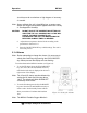
5. To disable the alarms set the high alarm set point above 100%.
Note: When the alarm is in the OFF condition (set point above
100%) the ALARM OFF status message blinks slowly on
the LCD below the oxygen readout.
2.1.5 Output 0-1 VDC or RS232
The MX300-I provides signal outputs for use with recorders and
computers. The instruments are supplied standard with a 0-1 VDC
output. An optional 0-1 VDC Interface Cable (P/N B-75554) is
available from Teledyne for this purpose.
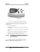
To connect the analyzer to an analog recording device:
1. Insert one end of the interface cable into the output port on
the side of the instrument. See Figure 2-9.
2. Insert the other end into the analog recorder device. Make
sure the device is equipped to handle a 0-1 VDC signal.
When properly calibrated, the output signal generated by the
analyzer is linear and proportional to the oxygen concentration.
If you requested Option-B (RS 232 digital output) at the time of
purchase, a digital RS 232 signal is output from the output port shown in
Figure 2-8. Use the optional RS 232 Interface Cable (P/N B-75555)
available from Teledyne for connection to a standard RS 232 port on a
computer or other suitably equipped digital device.